A thermal fatigue test device under simulated gas environment

A test device and thermal fatigue technology, which is applied in the field of aero-engines, can solve problems that cannot be applied to engineering applications, and achieve the effects of compact structure, energy-saving transportation, and improved test efficiency

Active Publication Date: 2018-04-10
BEIHANG UNIV
View PDF13 Cites 0 Cited by
  • Summary
  • Abstract
  • Description
  • Claims
  • Application Information

AI Technical Summary

Problems solved by technology

At present, the research on the oxidation behavior of thermal barrier coatings and superalloys is carried out in the atmospheric environment (resistance wire heating or electric eddy current heating is used when the air is still), and the gas contains S and insufficiently atomized fuel droplets. These components that are not available in the atmospheric test environment have a very important impact on the oxidation of superalloys and thermal barrier coatings; high-speed gas also has an erosion effect on thermal barrier coatings, so the superalloys and thermal barrier coating systems are studied in the atmospheric environment The damage data obtained by oxidation or thermal fatigue behavior can no longer meet the requirements of engineering applications

Method used


Image

  • A thermal fatigue test device under simulated gas environment
  • A thermal fatigue test device under simulated gas environment
  • A thermal fatigue test device under simulated gas environment

Examples


Embodiment Construction

[0023] The present invention will be described in detail below in conjunction with the accompanying drawings and embodiments.

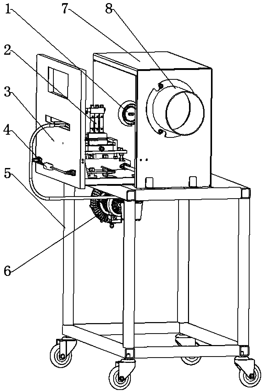
[0024] The invention provides a thermal fatigue test device under simulated gas environment, such as figure 1 As shown, the test device includes a burner 1 , a fixture 2 , a fixture support table 3 , a movable platform 12 , a support frame 5 , a blower 6 , a furnace body 7 and an exhaust device 8 . The bottom of the support frame 5 is equipped with universal casters, which is convenient for transportation and movement. A furnace body 7 is fixedly arranged on the support frame 5, a burner 1 and an exhaust device 8 are fixedly arranged on the left and right sides of the furnace body 7, and the high-temperature gas produced by the burner 1 heats the test piece 2-3 Then it is discharged through the exhaust device 8. Preferably, the burner 1 and the exhaust device 8 are arranged coaxially. The support frame 5 at the bottom of the body of furnace 7 can b...


PUM


Abstract

The invention discloses a thermal fatigue test device capable of simulating a gas environment, and belongs to the technical field of aircraft engines. The device comprises a burner, a fixture, a fixture support stage, a mobile platform, a support frame, a blower, a furnace body, and an exhaust device. The burner, the blower and the fixture are integrated on the furnace body. The furnace body is fixed on the support frame, and the support frame is connected with the fixture support stage through the mobile platform. The fixture is fixed on the fixture support stage. The burner and the exhaust device are disposed on the sides of the furnace body. During test, the blower always supplies high-pressure cooling air to the inside of a circular pipe test piece to produce a temperature gradient between the inside and the outside of the circular pipe test piece, so as to simulate the real working environment of a thermal barrier coating and high-temperature alloy. With the device, the load spectrum of the hot-end parts of an engine can be truly simulated, and the position of a test piece in the gas flame can be adjusted quickly in test. The device is compact in structure, energy-saving, and easy to transport.

Description

technical field [0001] The invention relates to the technical field of aero-engines, and is a thermal fatigue test device capable of simulating the real working environment of hot-end components of an aero-engine and suitable for aviation kerosene combustion. The test device can realize the test conditions of gas from room temperature to 1300°C, and can be used to simulate various working states of the aero-engine such as cold state, start-up, maximum state, and parking. In this way, it can be used to study the thermal fatigue behavior of engine hot-end components in gas environment, and can also be used to study the oxidation or thermal fatigue behavior of thermal barrier coatings in gas environment. Background technique [0002] The operating temperature of modern advanced aero-engine hot end components (T t4 ) is already close to 1600°C, and the temperature of the superalloy substrate used in the high-pressure turbine guide is 900°C to 1050°C after being insulated by the...

Claims


Application Information

Patent Timeline
Patent Type & Authority Patents(China)
IPC IPC(8): G01M13/00G01N25/00
CPCG01M13/00G01N25/00
Inventor 齐红宇张蜃之杨洪伟杨晓光
Owner BEIHANG UNIV
Why Eureka
Try Eureka