
Phase difference regenerative air preheater and preheating method

An air preheater and phase difference technology, applied in preheating, combustion methods, heat storage equipment, etc., can solve the problems of easy corrosion of heat exchange elements, lower heat exchange efficiency, and impact on safety, and achieve the level of equipment integration High, the equipment occupies a small area, and achieves the effect of stable pressure

Active Publication Date: 2016-08-24
YUEYANG ZHONGDING THERMAL ELECTROMAGNETIC TECH CO LTD
View PDF5 Cites 4 Cited by
  • Summary
  • Abstract
  • Description
  • Claims
  • Application Information

AI Technical Summary

Problems solved by technology

[0002] The air preheaters used in petrochemical flame heating furnace flue gas waste heat recovery, such as heat pipe type, tube type, cast iron plate type, glass plate type and other preheaters, all have certain shortcomings, such as: the exhaust gas temperature is limited by the low temperature dew point corrosion temperature If the temperature is controlled above the dew point, the heat exchange elements are prone to corrosion, the fouling efficiency decreases during use, element deformation and air leakage, medium deterioration and other reasons cause failure, heat exchange efficiency decreases, and equipment maintenance and repair costs are relatively high
Although the rotary regenerative air preheater developed in the application of petrochemical heating furnaces in recent years has high efficiency and stable equipment operation, it has a large investment and a large rotary size of the equipment, which causes difficulties in the transportation of the equipment body
[0003] However, the reversing regenerative air preheater used in other industries generally occupies a large area due to the need for pairs of regenerative boxes and the corresponding regenerative combustion system, and when the four-way valve is reversing Furnace pressure fluctuates greatly, and the risk of flameout and backfire during burner operation is high, which affects safety

Method used


Image

  • Phase difference regenerative air preheater and preheating method
  • Phase difference regenerative air preheater and preheating method
  • Phase difference regenerative air preheater and preheating method

Examples


Embodiment Construction

[0025] In order to facilitate the understanding of the present invention, the present invention will be described more fully below with reference to the associated drawings. A preferred embodiment of the invention is shown in the drawings. However, the present invention can be embodied in many different forms and is not limited to the embodiments described herein. Rather, these embodiments are provided so that the disclosure of the present invention will be thorough and complete.

[0026] It should be noted that when an element is considered to be “disposed” on another element, it may be directly disposed on or connected to the other element or there may be an intervening element at the same time.

[0027] Unless otherwise defined, all technical and scientific terms used herein have the same meaning as commonly understood by one of ordinary skill in the technical field of the invention. The terms used in the description are only for describing specific implementation purpose...


PUM


Abstract

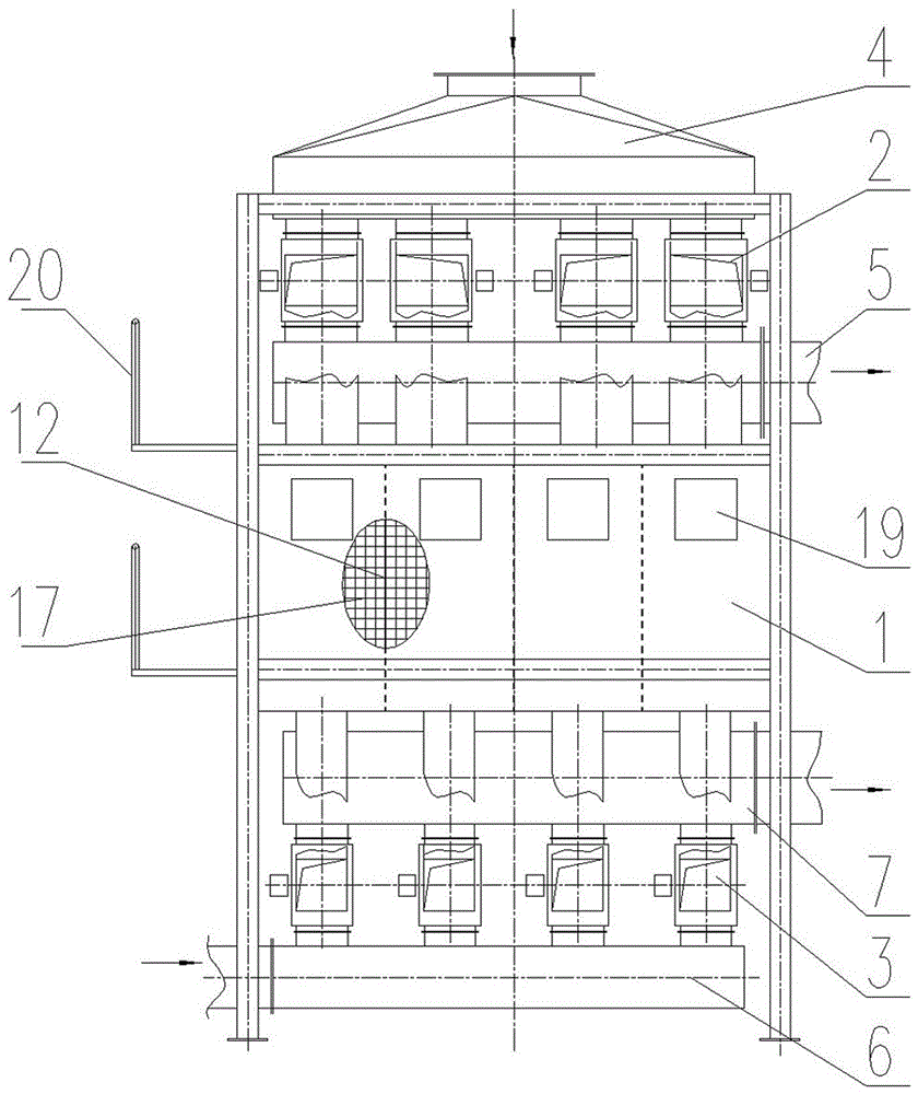
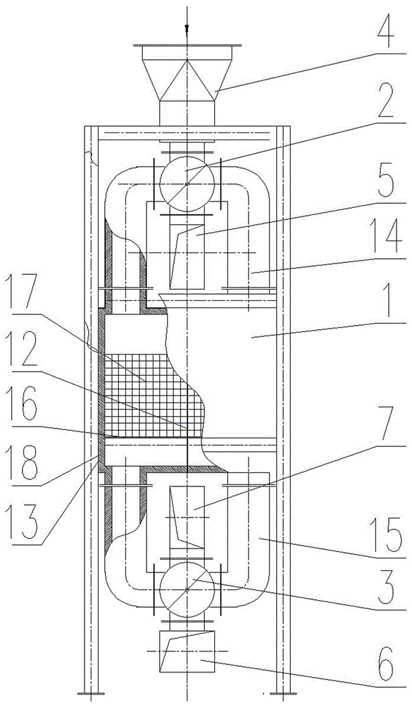
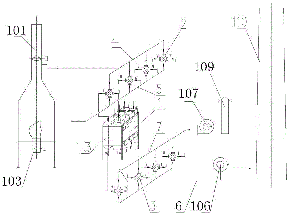
The invention discloses a phase difference regenerative air preheater. The preheater comprises a high-temperature flue, high-temperature four-way valves, a high-temperature air flue, a body, a low-temperature flue, low-temperature four-way valves and a low-temperature air flue which are arranged in a sequentially overlaid way from the upper part to the lower part, wherein the main body of the body is a heat storage tank; baffles are arranged inside the heat storage tank, so as to divide the heat storage tank into even numbered of regenerative chambers; an upper flue / air flue outlet is formed in the top of each regenerative chamber; a lower flue / air flue outlet is formed in the bottom of each regenerative chamber; the high-temperature four-way valves and the low-temperature four-way valves form a plurality of heat transfer units; the commutation cycle of all the heat transfer units are the same; the phase time difference of switching time exists between the high-temperature four-way valves and the low-temperature four-way valves and that of other heat exchange units, the application of the reversing regenerative air preheater pm a flue gas residual heat recycling device of a petrifaction heating furnace can be realized, and requirements on stable pressure and temperature for combustion air of a petrifaction heating furnace combustor are achieved.

Description

technical field [0001] The invention relates to an air preheating device and an air preheating method for recovering flue gas waste heat of a petrochemical flame heating furnace, in particular to a phase difference regenerative air preheater and the preheating method adopted therein. Background technique [0002] The air preheaters used in petrochemical flame heating furnace flue gas waste heat recovery, such as heat pipe type, tube type, cast iron plate type, glass plate type and other preheaters, all have certain shortcomings, such as: the exhaust gas temperature is limited by the low temperature dew point corrosion temperature If the temperature is controlled above the dew point, the heat exchange element is easily corroded, the scaling efficiency decreases during use, the element is deformed and leaks air, the medium deteriorates and other reasons cause failure, the heat exchange efficiency is reduced, and the equipment maintenance and repair cost is relatively high. Alt...

Claims


Application Information

Patent Timeline
Patent Type & Authority Applications(China)
IPC IPC(8): F22D1/00F27D17/00F23L15/00F28D20/02
CPCF22D1/00F23L15/00F27D17/004F27D2017/007F28D20/02Y02E20/34Y02E60/14
Inventor 游述怀罗映波周海明曹谦田海柏胡赤峰匡乐谭宠黄腾飞
Owner YUEYANG ZHONGDING THERMAL ELECTROMAGNETIC TECH CO LTD
Learn More