Air sealing body

A technology of air sealing body and sealing body, which is applied in the direction of closing devices, containers, packaging items, etc., can solve the problems of difficult opening and inflation at the opening point, inaccurate alignment, and unsmoothness, etc., and achieve fast, stable and effective air locking performance Effect

Inactive Publication Date: 2016-08-24
颜登坤
View PDF12 Cites 1 Cited by
  • Summary
  • Abstract
  • Description
  • Claims
  • Application Information

AI Technical Summary

Problems solved by technology

[0007] 1. Two connected heat-resistant zones or mesh air intake can effectively solve the problem that the opening point is difficult to open and the inflation is not smooth due to inaccurate alignment during the production process, so that the air can be aired quickly

Method used


Image

  • Air sealing body
  • Air sealing body
  • Air sealing body

Examples


Embodiment 1

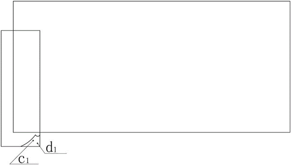
[0039] Embodiment 1: In a specific embodiment, there are two inner films that are automatically close to each other so as to block the air path. Add thermoplastic elastomer POE to the surface (c1 surface and d1 surface), and thermoplastic elastomer cannot be added to the outer layer, otherwise it will be difficult to process in the subsequent process.

[0040] After the inner film added with thermoplastic elastomer is heat-sealed and processed, the gas enters the airbag through the channel and can be automatically closed and closed to block the backflow of air. The two inner films of the original patent are extruded by the increase of internal air pressure. The membrane makes it tight and prevents backflow of air.

Embodiment 2

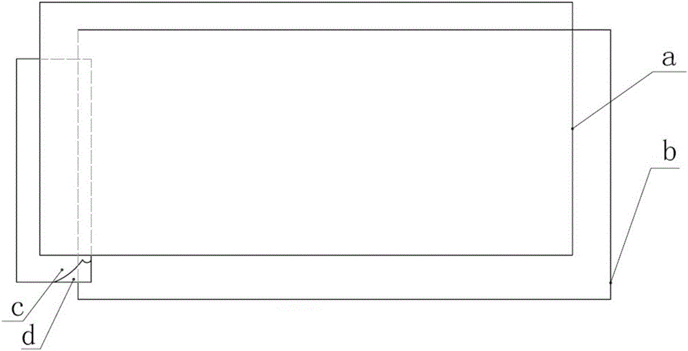
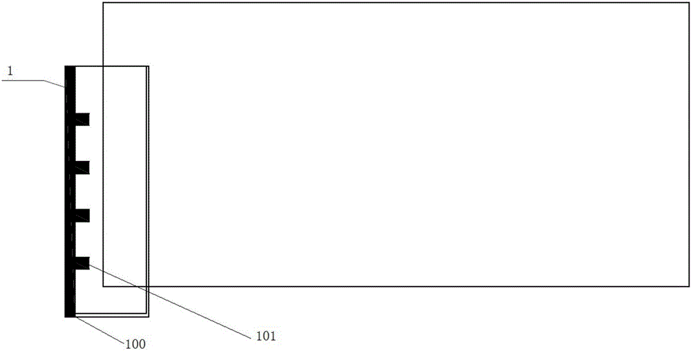
[0041] Embodiment 2: An air-tight body, comprising two outer membranes (a, b), two inner membranes (c, d), and thermoplastic elastomer POE added to the opposite side (c1, d1) of the two inner membranes; No thermoplastic elastomer POE is added to the other side of the sheet that is not in contact with the inner film. On the top of one of the opposite surfaces of the two inner films, a continuous strip or line of heat-resistant material is coated along the width direction to form the first heat-resistant material zone; the second heat-resistant material zone Communicating with the first heat-resistant material area, the first heat-resistant material area is coated with a plurality of second heat-resistant material areas at intervals as air intake channels; the first heat-resistant material area is not parallel to the second heat-resistant material area.

Embodiment 3

[0042] Embodiment 3: An air-tight body, comprising two outer membranes (a, b), two inner membranes (c, d), and thermoplastic elastomer POE added to the opposite side (c1, d1) of the two inner membranes; No thermoplastic elastomer POE is added to the other side of the sheet that is not in contact with the inner film. On the top of one of the opposite surfaces of the two inner films, a continuous strip or line of heat-resistant material is coated along the width direction to form a heat-resistant line; the second heat-resistant material area communicates with the heat-resistant line A plurality of second heat-resistant material areas are coated at intervals below the heat-resistant line as air intake passages; the first heat-resistant material area is not parallel to the heat-resistant line.


PUM


Abstract

The invention provides an air sealing body. According to the air sealing body, two communicated or non-communicated heat-resisting areas or a netted air inflow mode is utilized to achieve rapid air inflow. The air sealing body comprises two outer membranes and two inner membranes, the top end of the face, facing the other inner membrane, of one inner membrane is continuously coated with a heat-resisting material line, and then the lower part of the heat-resisting material line is coated with a heat-resisting material at equal intervals to serve as an air inflow channel; the inner membranes and the outer membranes are bonded with a heat sealing line rather than heat sealing points. Besides, thermoplastic elastomer POE can be arranged on the opposite faces of the inner membranes, and no thermoplastic elastomers POE is added to the other faces of the inner membranes; in the inflating process, the heat sealing line is pulled apart at the outer membrane parts due to expansion, and all air inflow openings are opened for rapid inflation; when air injection is completed, the two inner membranes with the thermoplastic elastomers POE added can be further used as sealing air valves and can be automatically sucked and tightly attached to achieve automatic sealing.

Description

technical field [0001] The invention relates to an air buffer package, in particular to an air buffer package that can be quickly inflated or / and automatically seal an air inlet without air leakage. Background technique [0002] At present, resin is used as a base material to make a sealing body and then inflated to form a cushioning packaging material. Due to its good cushioning effect and environmental protection features, it has been more and more recognized by the market. However, the original preparation method and technology on the one hand are inconvenient to operate and consume a lot of energy, and on the other hand, the method of blocking the air path by increasing the internal air pressure to make the inner membrane close to each other cannot effectively meet the requirements of air retention. [0003] The existing common manufacturing method has the patent number ZL200610067311.5, and there is another manufacturing method with the application number 200910128472.4...

Claims


Application Information

Patent Timeline
IPC IPC(8): B65D81/05B65D85/30B65D30/02B65D33/16
CPCB65D81/052B65D31/00B65D33/16B65D85/30
Inventor 颜登坤
Owner 颜登坤
Why Eureka
Try Eureka