
Miniature all-electric injection molding machine injection guide structure

A guiding structure, all-electric technology, applied in the field of mechanical transmission mechanism and guiding device, can solve the problems of insufficient precision and configuration, unstable guiding, etc., to reduce abnormal wear, improve the accuracy of plastic parts, and improve the service life.

Inactive Publication Date: 2016-08-24
BORCH MACHINERY
View PDF0 Cites 2 Cited by
  • Summary
  • Abstract
  • Description
  • Claims
  • Application Information

AI Technical Summary

Problems solved by technology

[0006] Beneficial effects of the present invention: the injection device involved in the present invention solves the problem of unstable guidance of the injection unit of the current all-electric injection molding machine due to the lack of precision and configuration of the injection action guide device, and uses direct simultaneous guidance to the front end of the injection rod and the lead screw The structure and mechanism ensure that the injection rod and the injection screw are coaxial and in the same direction during the injection process; reduce the abnormal wear of the material tube and the injection rod, increase the service life of the injection rod, and improve the precision of the plastic parts

Method used


Image

  • Miniature all-electric injection molding machine injection guide structure
  • Miniature all-electric injection molding machine injection guide structure
  • Miniature all-electric injection molding machine injection guide structure

Examples


Embodiment Construction

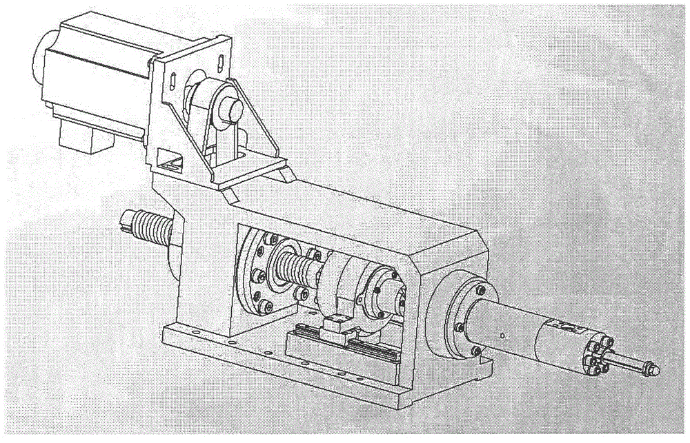
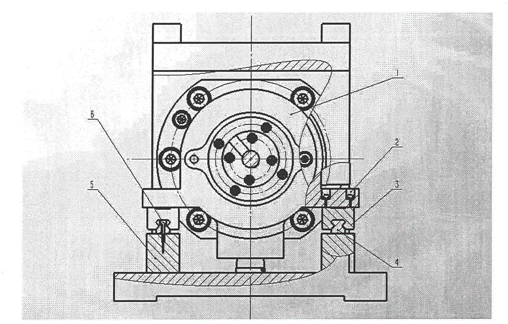
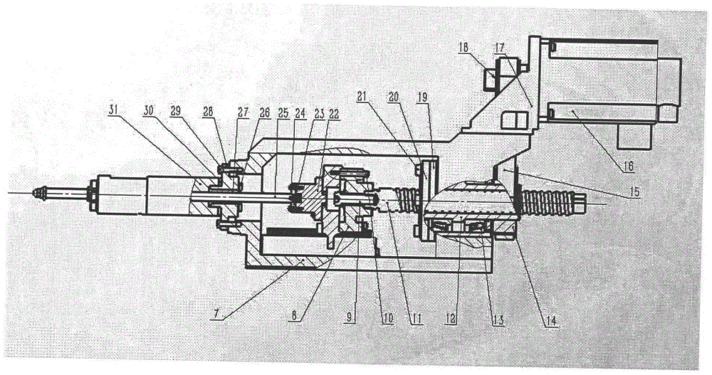
[0013] like figure 1 , figure 2 , image 3 , Figure 4 As shown, the injection guide device of the injection device in the injection unit of a miniature all-electric injection molding machine realizes the precise guidance of the injection screw and the injection rod through the guide rail and the injection guide plate. It includes the injection guide plate (1), the slider Bolts and washers (2), guide rail sliders (3), guide rails (4), guide rail backing plates (5), backing plate bolts and washers (6), injection brackets (7), tension pressure sensors (8), locking Bolt and washer (9), sensor bolt and washer (10), injection screw (11), injection screw nut (12), screw nut bearing (13), motor pulley (14), injection timing belt (15 ), injection motor (16), motor bracket (17), screw pulley (18), screw bearing housing (19), bearing housing flange (20), bearing housing bolts and washers (21), shooter housing (22), shot rod snap (23), snap bolt and washer (24), injection rod (25), ...


PUM


Abstract

The invention discloses a miniature all-electric injection molding machine injection guide structure. The injection guide structure comprises an injection guide plate, sliding block bolts and gaskets, a guide rail sliding block, a guide rail, a guide rail base plate, an injection support, a tension and pressure sensor, an injection screw, a screw nut bearing, a motor belt wheel, an injection synchronous belt, an injection motor, a motor frame, a screw belt wheel, a screw bearing seat, a bearing seat flange, an injection rod base, an injection rod snap joint, an injection rod, a transition guide sleeve, a material pipe flange, a material pipe, an injection advance limiting device and an injection reverse limiting device. The injection guide plate is connected to the guide rail sliding block. The guide rail sliding block fits to the guide rail. The guide rail sliding block slides back and forth on the guide rail along the guide rail. The guide rail is fastened to the guide rail base plate. The guide rail base plate is fixed to the injection support. One end surface of the injection guide plate is connected to the injection rod base. The injection rod base is connected to the injection rod. The injection screw and the tension and pressure sensor are coaxially connected. The end surface and the excircle of the tension and pressure sensor are connected to the injection guide plate.

Description

technical field [0001] The invention relates to a guiding and positioning structure for injection parts of an injection device of a miniature all-electric injection molding machine. The structure is used for the injection device of a miniature or small high-precision all-electric injection molding machine, and belongs to the technical field of mechanical transmission mechanisms and guide devices. Background technique [0002] The guide structure of the injection device of the existing all-electric injection molding machine is usually composed of an injection guide post and an injection copper sleeve located between the injection head plate, the injection moving plate and the injection tail plate; the injection guide post is fixed on the In the hole of the guide post on the injection head plate and the injection tail plate, the injection head plate is located at the front end of the injection guide post, the injection tail plate is located at the rear end of the injection guid...

Claims


Application Information

Patent Timeline
Patent Type & Authority Applications(China)
IPC IPC(8): B29C45/17
Inventor 李凯岭臧淑华
Owner BORCH MACHINERY
Learn More