
Wind-generating-set emergency power system based on fuel cell and working method

A technology of wind power generators and fuel cells, applied in solid electrolyte fuel cells, wind power generation, emergency power supply arrangements, etc., can solve problems such as remote location, increased operating costs and maintenance costs, pollution, etc., to extend backup time, run The effect of low maintenance cost

Inactive Publication Date: 2016-08-17
HUANENG CLEAN ENERGY RES INST
View PDF6 Cites 5 Cited by
  • Summary
  • Abstract
  • Description
  • Claims
  • Application Information

AI Technical Summary

Problems solved by technology

However, whether it is an onshore wind power plant or an offshore wind power plant, the geographical location is relatively remote, and diesel oil needs to be transported over a long distance, which greatly increases the operating and maintenance costs of diesel generator sets, and the efficiency of diesel generator sets is low and the pollution is serious.

Method used


Image

  • Wind-generating-set emergency power system based on fuel cell and working method

Examples


Embodiment 1

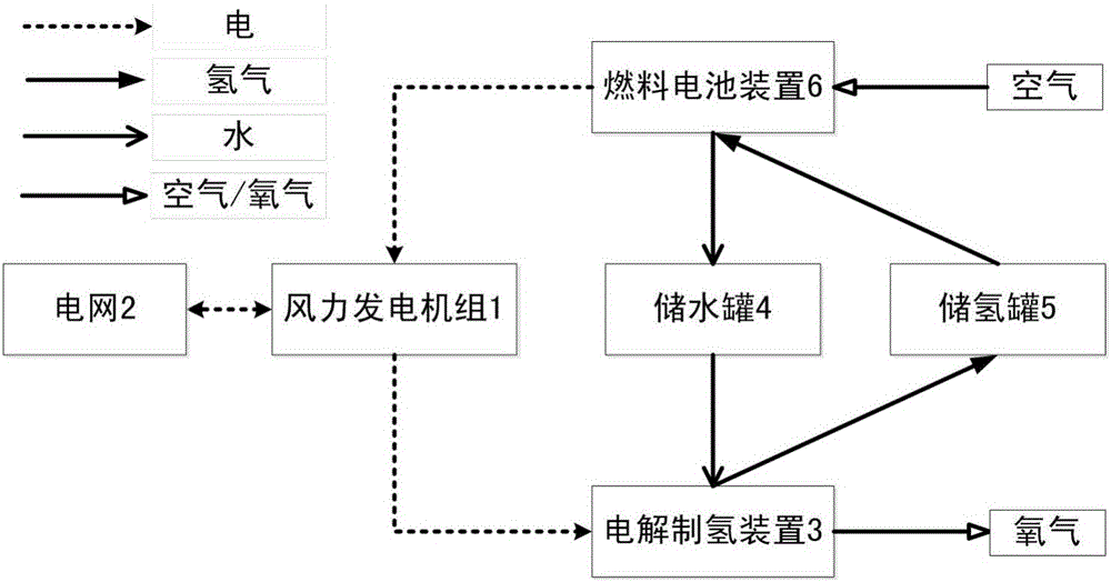
[0029] The wind turbine 1 works normally, part of the electric energy generated by the wind turbine 1 is sent to the grid 2, and part of it is input to the PEM electrolytic hydrogen production device 3, the power consumption is 40.8kW, the water consumption is 5.5L / h, and the hydrogen production capacity reaches 6Nm 3 / h, the pressure to generate hydrogen is 3MPa. The hydrogen produced by the PEM electrolytic hydrogen production device 3 is transported to the hydrogen storage tank 5, and the volume of the hydrogen storage tank 5 is 13.9m 3 , Design pressure 3.5MPa. The hydrogen storage tank 5 is fully stored after the electrolytic hydrogen production device 3 has been operated for 67 hours.

[0030] When the wind turbine 1 is not working and the power grid 2 is cut off, the PEMFC fuel cell device 6 uses the hydrogen in the hydrogen storage tank 5 and the oxygen in the air to generate electricity, with a power generation of 50kW, a power generation efficiency of 50% LHV, and ...

Embodiment 2

[0032] The wind turbine 1 works normally, part of the electric energy generated by the wind turbine 1 is sent to the grid 2, and part of it is input to the PEM electrolytic hydrogen production device 3, the power consumption is 408kW, the water consumption is 55L / h, and the hydrogen production capacity reaches 60Nm 3 / h, the pressure to generate hydrogen is 3MPa. The hydrogen produced by the PEM electrolytic hydrogen production device 3 is transported to the hydrogen storage tank 5, and the hydrogen storage tank 5 has 10 volumes of 13.9m 3 It is composed of a hydrogen storage tank with a design pressure of 3.5MPa. The hydrogen storage tank 5 is fully charged after the electrolytic hydrogen production device 3 has been operated for 67 hours.

[0033] When the wind power generator set 1 is not working and the power grid 2 is cut off, the fuel cell device 6 uses the hydrogen in the hydrogen storage tank 5 and the oxygen in the air to generate electricity, and the fuel cell device...


PUM

PropertyMeasurementUnit
poweraaaaaaaaaa

Abstract

The invention discloses a wind-generating-set emergency power system based on a fuel cell and a working method. The system comprises a wind generating set connected with a power grid, the electric energy output end of the wind generating set is connected with the electric energy input end of an electrolysis hydrogen production device, the water inlet end of the electrolysis hydrogen production device is connected with the water outlet end of a water storage tank, the hydrogen outlet end of the electrolysis hydrogen production device is connected with the hydrogen inlet end of a hydrogen storage tank, the oxygen outlet end of the electrolysis hydrogen production device is connected to atmosphere, the hydrogen outlet end of the hydrogen storage tank is connected with the hydrogen inlet end of a fuel cell device, the water outlet end of the fuel cell device is connected with the water inlet end of the water storage tank, and the fuel cell device further comprises an air inlet end. The invention further discloses a working method of the system. By means of the system and the working method, full-automatic running can be achieved, additional supplementing of fuel is avoided, and running and maintaining cost is low.

Description

technical field [0001] The invention belongs to the technical field of power generation, and in particular relates to a backup power supply system and working method of a fuel cell-based wind power generating set. Background technique [0002] With the rapid growth of the national economy, the demand for energy is increasingly strong, and the problems of energy shortage and environmental pollution caused by fossil energy are becoming increasingly acute. New energy resources have great potential and can be used sustainably. They have played an important role in meeting energy demand, improving energy structure, reducing environmental pollution, and promoting economic development, and have attracted widespread attention from the international community. Under the dual pressure of energy security and environmental protection, wind power technology, which is relatively mature in technology and qualified for large-scale development, has achieved rapid development worldwide as a c...

Claims


Application Information

Patent Timeline
Patent Type & Authority Applications(China)
IPC IPC(8): H02J9/06H01M8/10H02J3/38
CPCH01M8/10H02J3/386H02J9/06H02J2300/30Y02B10/70Y02B90/10Y02E10/76Y02E60/50
Inventor 许世森王洪建程健张瑞云王鹏杰任永强
Owner HUANENG CLEAN ENERGY RES INST
Learn More