
Floor reinforcing steel bar laying device

A technology for steel bars and floor slabs is applied in the field of floor steel bar layout devices, which can solve the problems affecting construction speed, slow speed, complicated floor steel bar positioning procedures, etc., and achieve the effects of improving construction efficiency, improving accuracy, and saving labor costs.

Active Publication Date: 2016-08-17
CSCEC STRAIT CONSTR & DEV
View PDF9 Cites 4 Cited by
  • Summary
  • Abstract
  • Description
  • Claims
  • Application Information

AI Technical Summary

Problems solved by technology

However, in the construction of cast-in-place slabs, the positioning procedure of the slab reinforcement is complicated and slow, which directly affects the construction speed.

Method used


Image

  • Floor reinforcing steel bar laying device
  • Floor reinforcing steel bar laying device
  • Floor reinforcing steel bar laying device

Examples


Embodiment Construction

[0017] The content of the present invention will be described in detail below in conjunction with the accompanying drawings and embodiments of the description:

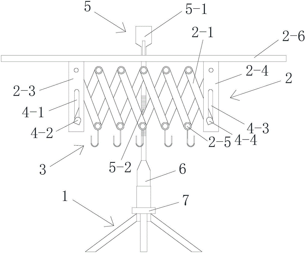
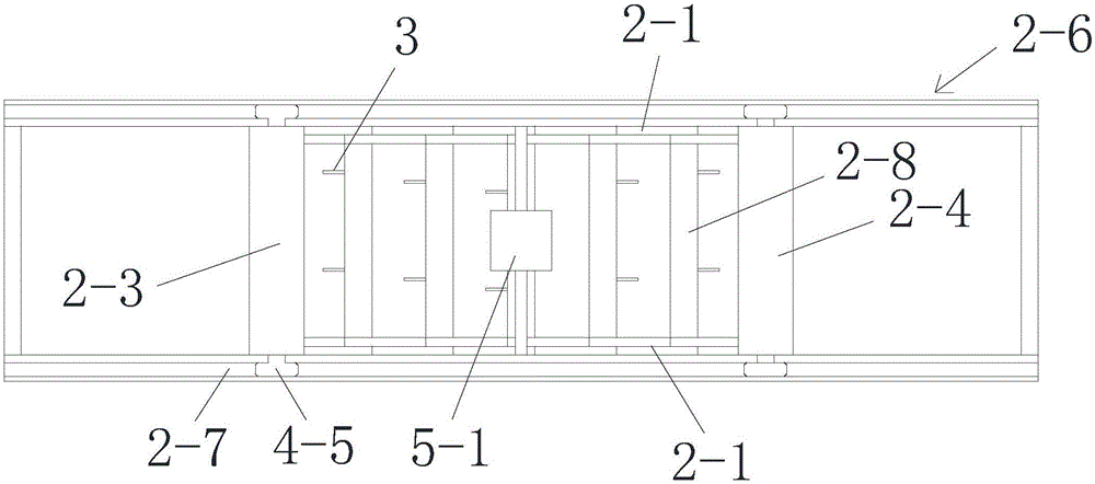
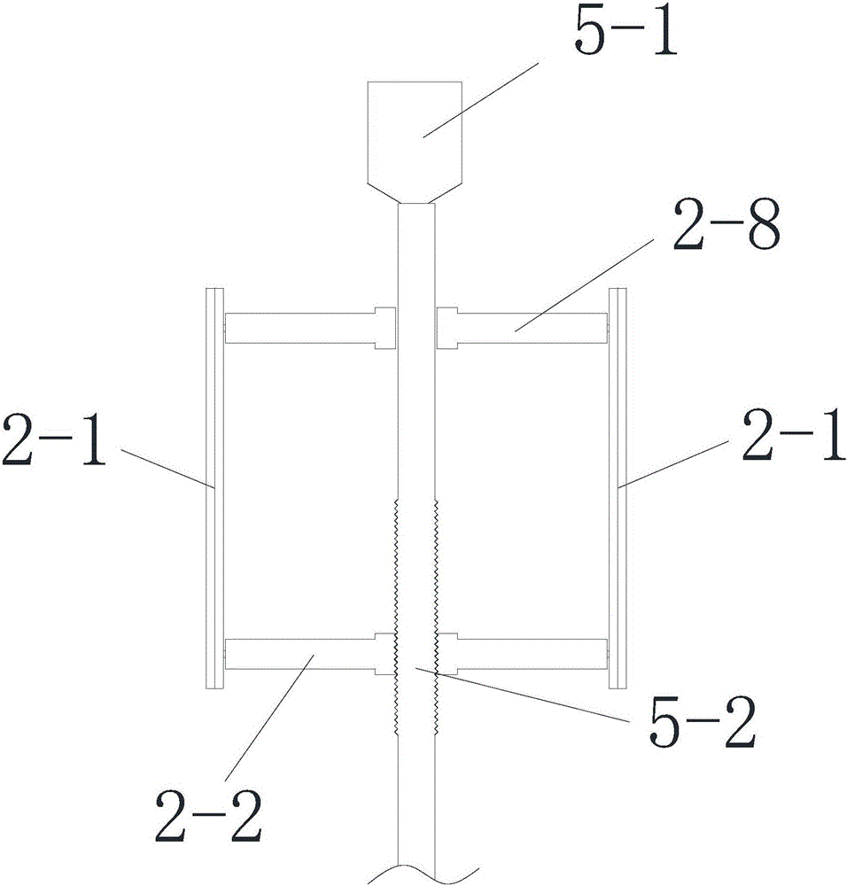
[0018] Such as Figures 1 to 7 Shown is a schematic diagram of an embodiment of a floor reinforcing bar laying device provided by the present invention.

[0019] A device for laying steel bars on a floor, which includes a base 1, a horizontal frame 2 arranged on the base 1 and telescopic in the horizontal direction, and several steel bar hook groups fixed on the horizontal frame 2 and distributed at intervals along the telescopic direction of the horizontal frame 2; The steel bar hook group includes more than two steel bar hooks 3 arranged at intervals, and the connection line of the same group of steel bar hooks 3 is perpendicular to the stretching direction of the horizontal frame 2 .

[0020] The floor steel bars 8 are placed on the same group of steel bar hooks 3, and the floor steel bars 8 are arranged at interv...


PUM


Abstract

The invention relates to a floor reinforcing steel bar laying device. The floor reinforcing steel bar laying device comprises a base, a horizontal frame which is arranged on the base and extends and retracts along the horizontal direction and a plurality of reinforcing steel bar hook sets which are fixedly arranged on the horizontal frame and are distributed at intervals along the extending-retracting direction of the horizontal frame, wherein each reinforcing steel bar hook set comprises more than or equal to two reinforcing steel bar hook sets which are arranged at intervals. The invention aims at providing a floor reinforcing steel bar laying device which can effectively improving floor reinforcing steel bar laying construction quality and efficiency. The floor reinforcing steel bar laying device has the advantages that the reinforcing steel bar hook sets distributed at intervals are arranged, and a retractable horizontal frame is used for adjusting distribution position of the reinforcing steel bar hook sets, so that large-area reinforcing steel bar layout can be completed by one time, workers do no need to bend down to put reinforcing steel bars one by one, floor reinforcing steel bar laying construction quality is greatly improved, and labor cost is greatly saved. A shear-fork type structure is adopted for controlling extension and retraction of the horizontal frame, same intervals between the reinforcing steel bar hook sets can be guaranteed, and reinforcing steel bar location accuracy is improved.

Description

technical field [0001] The invention relates to the field of building construction, in particular to a floor reinforcement laying device. Background technique [0002] With the rapid development of the construction industry, almost all modern buildings use cast-in-place slabs. However, in the construction of cast-in-place slabs, the positioning procedure of the slab reinforcement is complicated and slow, which directly affects the construction speed. Contents of the invention [0003] The object of the present invention is to provide a floor reinforcement laying device, which can effectively improve the construction quality and efficiency of floor reinforcement laying, and save labor costs. [0004] The purpose of the present invention is achieved through the following technical solutions: a floor steel bar laying device, which includes a base, a horizontal frame that is arranged on the base and expands and contracts in the horizontal direction, and several horizontal fra...

Claims


Application Information

Patent Timeline
Patent Type & Authority Applications(China)
IPC IPC(8): E04G21/12
CPCE04G21/12
Inventor 陈兵
Owner CSCEC STRAIT CONSTR & DEV
Learn More