Hydraulic floating workpiece support

A workpiece and hydraulic technology, applied in the field of hydraulic floating workpiece support, can solve the problems of cumbersome, difficult processing and high cost, and achieve the effect of solving the operation process

Inactive Publication Date: 2018-01-02
CHANGCHUN HONGSHUN AUTO FITTINGS CO LTD
View PDF9 Cites 0 Cited by
  • Summary
  • Abstract
  • Description
  • Claims
  • Application Information

AI Technical Summary

Problems solved by technology

[0002] Commonly used drilling, milling, machining centers, various gantry equipment, etc., the general small units are still using the most primitive methods of tightening with top screws and nuts, and even with gaskets and wedges. , Now some of our large units and those other developed countries use a steel ball sandwiched between the outer cone and the inner cone on mass-produced equipment, and use hydraulic pressure to jack up the top column so that the top surface of the top column is close to the workpiece Finally, the hydraulic pressure is transmitted to the top surface of the big head of the outer cone sleeve, and the top surface is pressurized so that the large cone sleeve goes down and rubs the interlayer steel ball, extruding the inner cone block to hug the top column tightly, and there is also a hydraulic pressurized plastic seal There are a lot of disadvantages such as locking the top column with the lattice copper ring tightly, and the tight support with the top screw and the nut and the tight support with the gasket and the wedge are easy to loosen and the operation is cumbersome, such as the hydraulic jack After lifting the jacking shaft, pressurize the top surface of the big head of the outer taper sleeve and rub the steel ball between the inner cone block to squeeze and lock the jacking column. The method is difficult to process, high cost, and the locking force is not good. For example, hydraulic pressure is used. The plastic sealing sleeve tightly hugs the lattice copper ring to lock the support of the top column, and the lack of bottom force affects the support force

Method used


Image

  • Hydraulic floating workpiece support
  • Hydraulic floating workpiece support
  • Hydraulic floating workpiece support

Examples


Embodiment 1

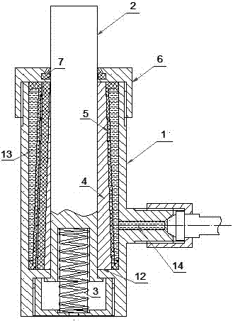
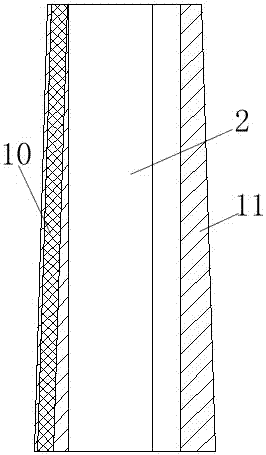
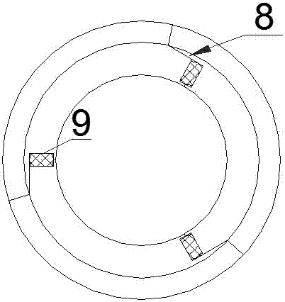
[0024] Such as figure 1 When the work is shown, the top surface of the top column 2 is pressed down by the gravity of the workpiece. After overcoming the supporting force of the weak spring 3 and moving down to a stable position, the hydraulic switch is turned on. The hydraulic oil enters the hydraulic oil chamber from the oil inlet 14, and the pressure transmission sealing sleeve 5 After being under pressure, its inner wall exerts pressure on the tight hoop iron block 4, so that the support spring frame 9 of the tight hoop iron block 4 squeezes the rubber strip support spring 10 to deform it, and shrinks the 3 bar-shaped iron blocks of the tight hoop iron block 4 At the same time, the seam shielding sheet 8 covers the gap between the bar-shaped iron blocks of the tight hoop iron block 4 to resist the pressure transmission sealing sleeve 5 from being squeezed by the hydraulic oil into the bar-shaped iron block of the tight hoop iron block 4 In the gap, the expansion force of t...

Embodiment 2

[0028] Such as figure 1 When the work is shown, the top surface of the top column 2 is pressed down by the gravity of the workpiece. After overcoming the supporting force of the weak spring 3 and moving down to a stable position, the hydraulic switch is turned on, and the hydraulic oil enters the hydraulic oil chamber 13 from the oil inlet 14, and the pressure transmission sealing sleeve 5. After being under pressure, its inner wall exerts pressure on the tight hoop iron block 4, so that the support spring frame 9 of the tight hoop iron block 4 extrudes the rubber strip support spring 10 to make it deformed, and the 5 bar-shaped iron blocks of the tight hoop iron block 4 are reduced. At the same time, the seam mask 8 covers the gap between the bar-shaped iron blocks of the tight hoop iron block 4 to resist the pressure transmission sealing sleeve 5 from being squeezed by the hydraulic oil into the bar-shaped iron block of the tight hoop iron block 4 In the gap between them, th...

Embodiment 3

[0030] Such as figure 1 When the work is shown, the top surface of the top column 2 is pressed down by the gravity of the workpiece. After overcoming the supporting force of the weak spring 3 and moving down to a stable position, the hydraulic switch is turned on, and the hydraulic oil enters the hydraulic oil chamber from the oil inlet 14, and the pressure transmission sealing sleeve 5 After being under pressure, its inner wall exerts pressure on the tight hoop iron block 4, so that the support spring frame 9 of the tight hoop iron block 4 squeezes the rubber strip support spring 10 to deform it, and reduces the 4 bar-shaped iron blocks of the tight hoop iron block 4 At the same time, the seam shielding piece 8 covers the gap between the bar-shaped iron blocks of the tight hoop iron block 4 to resist the pressure transmission sealing sleeve 5 from being squeezed by the hydraulic oil into the bar-shaped iron block of the tight hoop iron block 4 In the gap, the expansion force ...


PUM


Abstract

The invention relates to a hydraulic floating workpiece support. The support is characterized in that a top column penetrates through a center hole of a step in a shell, a bottom hole of the top column is held up through a weak spring to ascend to the highest point, a tightening iron block is composed of three to five equal-width bar-shaped iron blocks, the tightening iron block formed by combining the bar-shaped iron blocks is a cone, the stress area of the large head of the tightening iron block is two to three times of that of the small head of the tightening iron block, the periphery of the tightening iron block is sleeved with a pressure transferring sealing sleeve, the bar-shaped iron blocks of the tightening iron block are covered with a seam shielding piece on the bar-shaped iron blocks of the tightening iron block, and a gap is reserved between every two bar-shaped iron blocks. The support is easy and convenient to operate, supporting force is large, and stable recoil and centripetal force can hold on the hydraulic floating workpiece support vertically supported by the top column.

Description

technical field [0001] The invention relates to a hydraulic floating workpiece support, which belongs to the field of mechanical manufacturing. Background technique [0002] Commonly used drilling, milling, machining centers, various gantry equipment, etc., the general small units are still using the most primitive methods of tightening with top screws and nuts, and even with gaskets and wedges. , Now some of our large units and those other developed countries use a steel ball sandwiched between the outer cone and the inner cone on mass-produced equipment, and use hydraulic pressure to jack up the top column so that the top surface of the top column is close to the workpiece Finally, the hydraulic pressure is transmitted to the top surface of the big head of the outer cone sleeve, and the top surface is pressurized so that the large cone sleeve goes down and rubs the interlayer steel ball, extruding the inner cone block to hug the top column tightly, and there is also a hydr...

Claims


Application Information

Patent Timeline
Patent Type & Authority Patents(China)
IPC IPC(8): B23Q3/00
CPCB23Q3/00
Inventor 刘恩宏刘国方
Owner CHANGCHUN HONGSHUN AUTO FITTINGS CO LTD
Why Eureka
Try Eureka