
Cooking range generating steam by using waste heat

A technology of steam and stove, applied in the field of kitchen utensils, can solve the problems of insufficient utilization of heat, low utilization rate of waste heat, slow steam generation speed, etc., and achieves good promotion prospects, guarantees recovery and uniform distribution.

Active Publication Date: 2016-08-10
JIANGSU SHENGONG STOVE CO LTD
View PDF8 Cites 6 Cited by
  • Summary
  • Abstract
  • Description
  • Claims
  • Application Information

AI Technical Summary

Problems solved by technology

Although such a heating method can also achieve the purpose of heating the cooker, the heat generated by the flame and the high-temperature flue gas will overflow from the gap between the bottom of the pot and the stove, and the heat will not be fully utilized, resulting in a waste of energy.
In the existing market, some stoves have been improved, and the waste heat of the flue gas of the stove can be used to generate hot water or steam, etc., but the heat transfer efficiency is low, and the utilization rate of waste heat is not high, resulting in the speed of steam generation. Slow, the effect is not obvious; and the existing steam energy-saving stoves need to manually add water regularly, otherwise it is easy to appear the phenomenon of dry burning, resulting in certain restrictions on the promotion of such products

Method used


Image

  • Cooking range generating steam by using waste heat
  • Cooking range generating steam by using waste heat
  • Cooking range generating steam by using waste heat

Examples


Embodiment Construction

[0021] The present invention will be described in further detail below in conjunction with the accompanying drawings and specific embodiments.

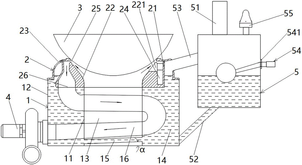
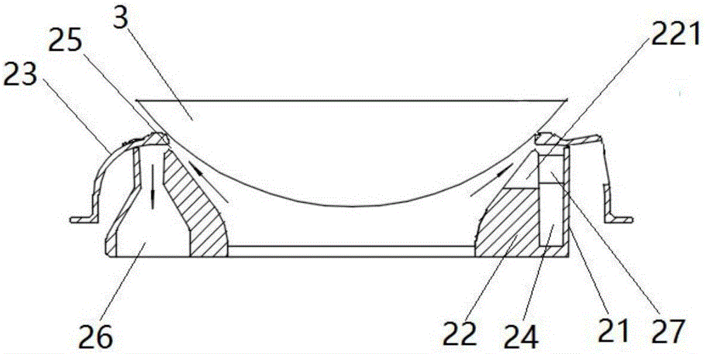
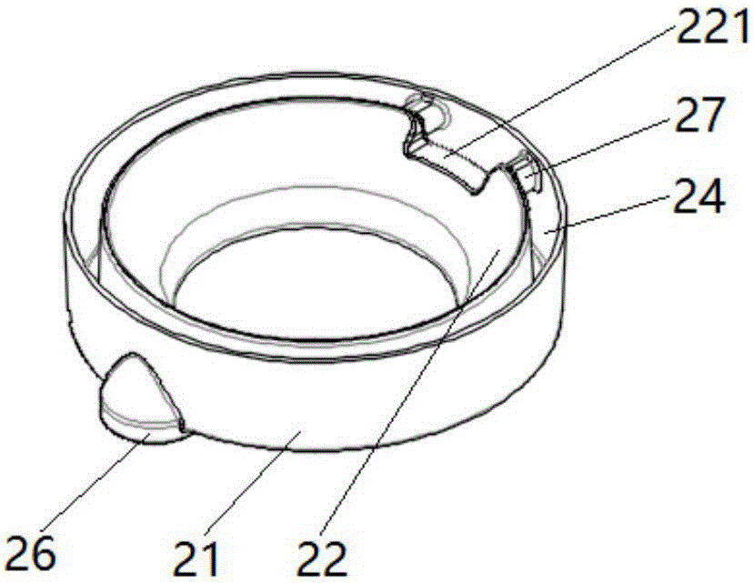
[0022] like figure 1 As shown, the cooking range of the present invention that utilizes waste heat to generate steam includes a furnace body 1 disposed above the furnace body 1 for supporting a burner 2 for cooking utensils 3, a water tank 5 for adding water 1 to the furnace body, and a Suction fan 4 for exhausting smoke. The furnace body 1 is composed of an inner furnace wall 11 and an outer furnace wall 12. The hollow area surrounded by the inner furnace wall 11 is a furnace hearth 13. The furnace head 2 includes an outer furnace ring 21 and an inner furnace ring 22. And the pot support ring 23, the bottom end of the inner furnace ring 22 is connected with the inner furnace wall 11, the bottom end of the pot support ring 23 is connected with the outer furnace wall 12, the inner furnace wall 11, the outer furnace wall The cavity fo...


PUM


Abstract

The invention relates to a cooking range generating steam by using waste heat. The cooking range a furnace body, a furnace head and a water tank, wherein the furnace body is combined by an inner furnace wall and an outer furnace wall; a hollow region surrounded by the inner furnace wall is a hearth; a plurality of tubular fire bars are uniformly arranged below the hearth at intervals in the furnace body; the furnace head comprises an outer furnace ring, an inner furnace ring and a pot body supporting ring; the lower end of the inner furnace ring is connected to the inner furnace wall; the lower end of the pot body supporting ring is connected to the outer furnace wall; a cavity among the inner wall furnace, the outer wall furnace and the furnace head is a heating cavity; a coil surrounding the hearth is arranged in the heating cavity; a steam pipe communicating with the top of the heating cavity is arranged in the upper part of the water tank; a water outlet pipe communicating with the bottom of the heating cavity is arranged in the lower part of the water tank; a gas outlet pipe is arranged on the top of the water tank; a water inlet is formed between the steam pipe and the water outlet pipe on the water tank; and a float ball water inlet valve is arranged on the water inlet. The cooking range provided by the invention realizes efficient recovery of smoke heat and automatic control of water inflow in a stove using process.

Description

technical field [0001] The invention relates to kitchen utensils, in particular to a stove for generating steam by using waste heat. Background technique [0002] The heating principle of traditional stoves is to heat the bottom of the pot by directly burning fuel through the atmosphere. Although such a heating method can also achieve the purpose of heating the cooker, the heat generated by the flame and the high-temperature flue gas will overflow from the gap between the bottom of the pot and the stove, and the heat will not be fully utilized, resulting in a waste of energy. In the existing market, some stoves have been improved, and the waste heat of the flue gas of the stove can be used to generate hot water or steam, etc., but the heat transfer efficiency is low, and the utilization rate of waste heat is not high, resulting in the speed of steam generation. Slow, the effect is not obvious; and the existing steam energy-saving stoves need to manually add water regularly,...

Claims


Application Information

Patent Timeline
IPC IPC(8): F27D17/00F22B1/08F22B35/00F24C15/00
CPCF22B1/08F22B35/00F24C15/00F27D17/001F27D17/002F27D17/004Y02P10/25
Inventor 顾加华杨熠杨红顾加荣董亚兵崔暇
Owner JIANGSU SHENGONG STOVE CO LTD
Learn More