Nanosecond grade digital synchronizer based on FPGA high-speed serial bus

A high-speed serial bus, synchronous machine technology, applied in synchronous transmitters, synchronous devices, digital transmission systems, etc., can solve the problems of narrow delay range, cumbersome methods, large area, etc., to achieve a wide delay range and reduce volume , the effect of small size

Inactive Publication Date: 2016-08-03
INST OF APPLIED ELECTRONICS CHINA ACAD OF ENG PHYSICS
View PDF5 Cites 7 Cited by
  • Summary
  • Abstract
  • Description
  • Claims
  • Application Information

AI Technical Summary

Problems solved by technology

[0002] In large-scale high-energy physics scientific experiments, due to the influence of installation location, operating environment, and other factors, and the length of transmission cables for each synchronous trigger signal is different, each trigger signal has a delay and cannot arrive synchronously. To solve the high-precision synchronous triggering of multiple physical experiment devices or multiple channels, it is necessary to develop a multi-channel digital synchronization machine
[0003] The current delay synchronization machine has the following problems: (1) It is realized by artificially adjusting the length of the transmission cable of each signal. This method is cumbersome, the accuracy is not high, and the delay cannot be automatically controlled and adjusted; (2) 2007 "Research on High-precision Digital Synchronizer for Ultra-short Laser Pulse Technology" in December 2009, using 8253 counters and analog interpolation delay technology to achieve high-precision delay with a delay accuracy of 1ns, and the output pulse Shake value ≤ 500ps, using the counter method to achieve 1ns delay accuracy, the operation process is too complicated
[0004] The delay accuracy of the utility model of CN201893762.U is 1ns, but from the technical scheme of realization, the utility model of CN201893762.U is realized by the method of FPGA+high-precision digital delay line, and the area of ​​the device is relatively large. And the delay range is narrow

Method used


Image

  • Nanosecond grade digital synchronizer based on FPGA high-speed serial bus
  • Nanosecond grade digital synchronizer based on FPGA high-speed serial bus

Examples


Embodiment Construction

[0026] In order to clearly understand the technical solution of the present invention, its detailed structure will be presented in the following description. Obviously, the implementation of the embodiments of the invention is not limited to specific details familiar to those skilled in the art. The preferred embodiments of the present invention are described in detail below, and there may be other implementations besides those described in detail.

[0027] The present invention will be described in further detail below in conjunction with the accompanying drawings and embodiments.

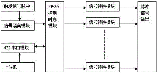
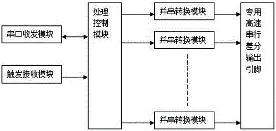
[0028] The present invention is a nanosecond-level digital synchronization machine based on FPGA high-speed serial bus, which is provided for high-precision synchronization and pulse width modulation within a wide delay range of multiple devices. figure 1 , the digital synchronous machine includes a trigger signal module, a signal isolation module, an FPGA control timing module, a signal conversi...


PUM


Abstract

The invention discloses a nanosecond grade digital synchronizer based on a FPGA high-speed serial bus. The digital synchronizer comprises a starting signal module, a signal isolation module, a FPGA control time sequence module, a signal conversion module and a pulse signal output module which are electrically connected in order; the FPGA control time sequence module is connected with an upper computer through a 422 serial port module; the technical scheme implement the synchronous triggering and pulse width modulation of multipath pulses with delay precision of 1ns, the digital synchronizer is small in volume, wide in delay range, adjustable in pulse width, and capable of meeting different requirements of synchronous triggering of a plurality of large physical devices.

Description

technical field [0001] The invention relates to the technical field of digital control, in particular to a nanosecond-level digital synchronization machine based on FPGA high-speed serial bus. Background technique [0002] In large-scale high-energy physics scientific experiments, due to the influence of installation location, operating environment, and other factors, and the length of transmission cables for each synchronous trigger signal is different, each trigger signal has a delay and cannot arrive synchronously. To solve the high-precision synchronous triggering of multiple physical experiment devices or multiple channels, it is necessary to develop a multi-channel digital synchronization machine. [0003] The current delay synchronization machine has the following problems: (1) It is realized by artificially adjusting the length of the transmission cable of each signal. This method is cumbersome, the accuracy is not high, and the delay cannot be automatically controll...

Claims


Application Information

Patent Timeline
IPC IPC(8): H03K5/131H04L7/00
CPCH03K5/131H04L7/0091
Inventor 卓红艳刘志强孟凡宝胡进光葛成良彭文张家如
Owner INST OF APPLIED ELECTRONICS CHINA ACAD OF ENG PHYSICS
Why Eureka
Try Eureka