
Inertia piezoelectric driving motor

A piezoelectric drive and inertial technology, applied in the direction of piezoelectric effect/electrostrictive or magnetostrictive motors, generators/motors, electrical components, etc., can solve the problems of piezoelectric motors such as weak tolerance and short life

Active Publication Date: 2016-08-03
谐振机电精密技术(苏州)有限公司
View PDF4 Cites 4 Cited by
  • Summary
  • Abstract
  • Description
  • Claims
  • Application Information

AI Technical Summary

Problems solved by technology

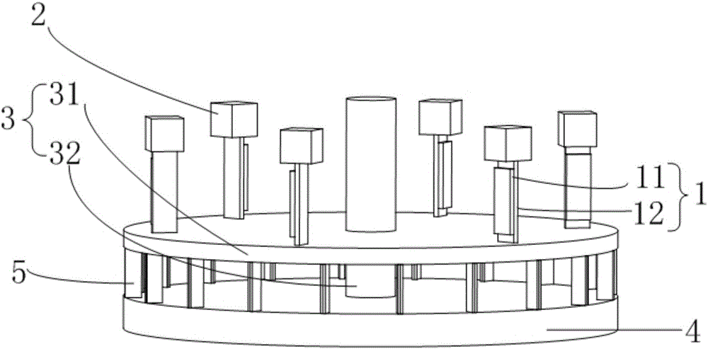
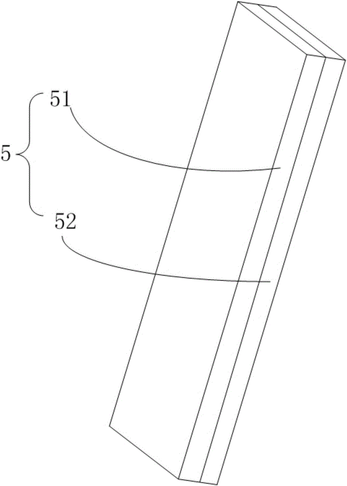
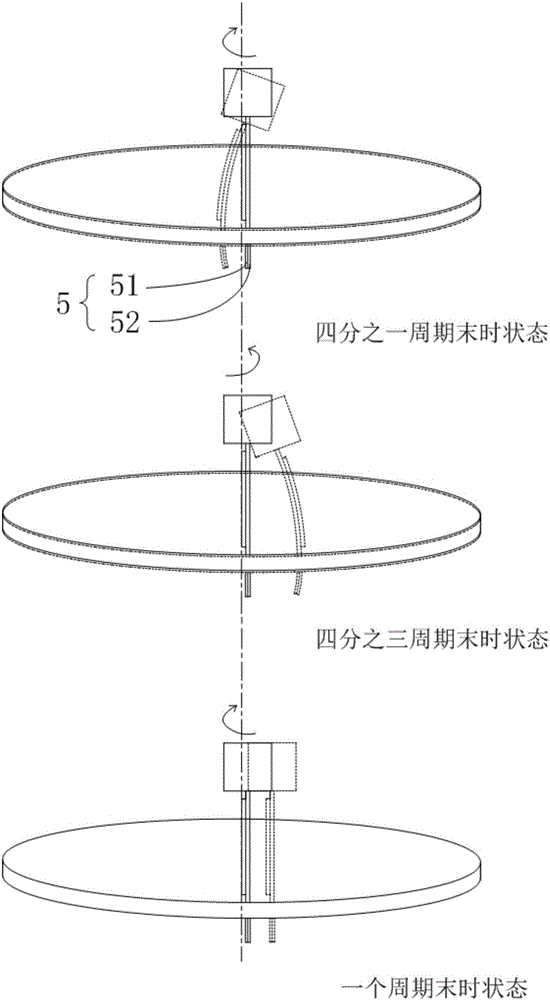
[0003] In order to solve the problems of weak tolerance and short service life of existing piezoelectric motors, an inertial piezoelectric drive motor is proposed, which is composed of a piezoelectric vibrator, a mass block, a rotating table, a base and a composite cantilever. After alternating current, reciprocating bending deformation is generated and the mass block is driven to vibrate. The inertial force causes the composite cantilever to bend and deform. Combining the effects of two materials with different friction coefficients on the composite cantilever, the friction force experienced by the composite cantilever when it rotates clockwise and counterclockwise within one cycle Different, the total rotation angle of the motor when the composite cantilever is subjected to a small friction force is greater than the total rotation angle when the friction force is large, so at the end of a cycle, the motor rotates in the direction where the composite cantilever is subjected to a small friction force

Method used


Image

  • Inertia piezoelectric driving motor
  • Inertia piezoelectric driving motor
  • Inertia piezoelectric driving motor

Examples


Embodiment Construction

[0010] Reference figure 1 with figure 2 , Including a piezoelectric vibrator 1, a mass 2, a rotating table 3, and a base 4, and is characterized in that it also includes a composite cantilever 5 formed by laminating two materials, wherein both ends of the piezoelectric vibrator 1 are fixedly connected to the The mass 2 and the rotating disc 31; the rotating table 3 includes two parts of the rotating disc 31 and the rotating shaft 32, the rotating disc 31 and the rotating shaft 32 are fixedly connected, and the axis of the rotating shaft 32 is vertical On the upper surface of the rotating disc 31; the piezoelectric vibrator 1 is composed of a piezoelectric ceramic 11 and an elastic substrate 12 bonded together, and the bonding surface of the piezoelectric ceramic 11 and the elastic substrate 12 and the rotating disc The upper surface of 31 is vertical, and the bonding surface of the piezoelectric ceramic 11 and the elastic substrate 12 exceeds the diameter of the rotating disc...


PUM


Abstract

The invention relates to an inertia piezoelectric driving motor. The inertia piezoelectric driving motor comprises piezoelectric vibrators, mass blocks, a rotating table, a base and a composite cantilever, wherein the two ends of each piezoelectric vibrator are fixedly connected to the corresponding mass block and a rotating disc; the rotating table comprises the rotating disc and a rotating shaft; the composite cantilever is of a sheet structure and formed by laminating a high-friction elastic material and a low-friction elastic material, the high-friction elastic material and the low-friction elastic material are the same in size and different in friction coefficient, the composite cantilever is fixedly connected to the lower surface of the rotating disc, and the laminating surface of the high-friction elastic material and the low-friction elastic material passes through the diameter of the rotating disc; the base and the rotating shaft form a rotation pair, the piezoelectric vibrators drive the mass blocks to vibrate, and the composite cantilever bends due to inertia and does rotating motion as the two materials are different in friction coefficient. The inertia piezoelectric driving motor has the advantages of being long in service life, high in fault tolerance, low in precision requirement and the like.

Description

Technical field [0001] The invention belongs to the field of piezoelectric driving, and specifically relates to an inertial piezoelectric driving motor. Background technique [0002] In recent years, with the rapid development of micro-nano technology, research in optical engineering, microelectronics manufacturing, aerospace technology, ultra-precision machinery manufacturing, biomedicine and other technical fields urgently needs drivers with strong tolerance and simple structure. With the development of science and technology, people have developed a new type of motor composed of functional materials to achieve ultra-precision drive. In recent years, this research has achieved a series of results, such as memory alloy motors, piezoelectric effect motors, electrostrictive motors, and magnetic motors. Telescopic motor, etc. Among them, piezoelectric materials (PZT) have the advantages of convenient control, high power density, high displacement resolution, good frequency respons...

Claims


Application Information

Patent Timeline
Patent Type & Authority Applications(China)
IPC IPC(8): H02N2/12
CPCH02N2/12
Inventor 吴越杨志刚刘庆萍王京春王旭宋正义
Owner 谐振机电精密技术(苏州)有限公司
Learn More