
Chips and Electronic Devices

A chip and bare chip technology, applied in the direction of circuits, printed circuits, electrical components, etc., can solve the problems of small winding space, limited space, increased production and design costs of electronic equipment, and achieve the effect of simplifying the difficulty of wiring

Active Publication Date: 2018-07-03
HUAWEI TECH CO LTD
View PDF4 Cites 0 Cited by
  • Summary
  • Abstract
  • Description
  • Claims
  • Application Information

AI Technical Summary

Problems solved by technology

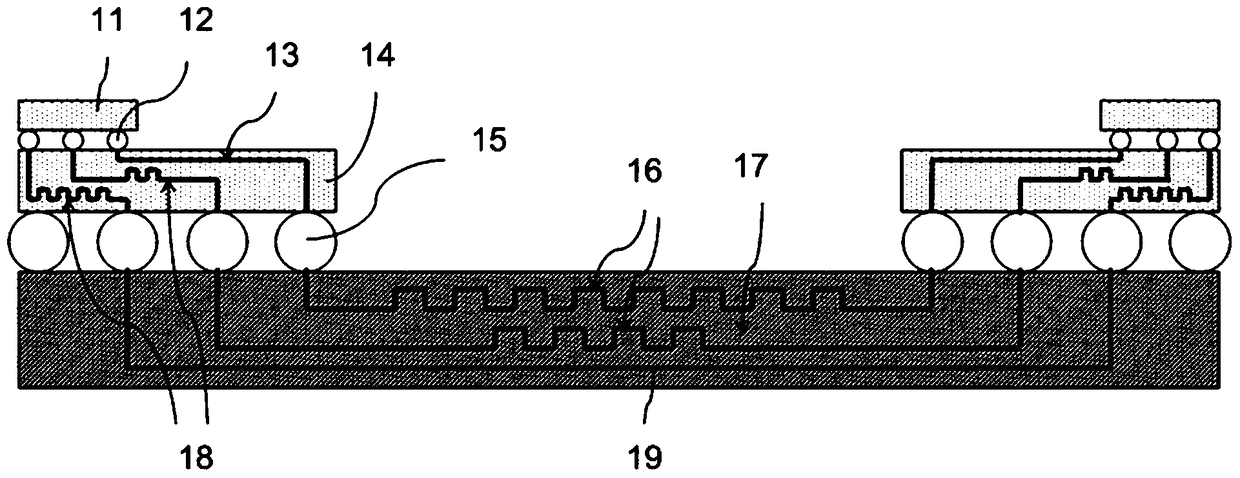
like figure 1 In such an arrangement method, a large amount of wiring space must be reserved in the chip substrate 14 and the printed circuit board 17, especially the small size of the substrate 14 has limited wiring space, and more wiring layers may be required to realize the wiring of signal lines, etc. Long control, which will lead to an increase in the number of substrate layers, which is not conducive to the cost control of the chip
Moreover, electronic equipment manufacturers need to use various means to obtain the delay of each path on both sides of the chip and the printed circuit board, and set up wiring for each path separately, which greatly increases the production and design costs of electronic equipment.

Method used


Image

  • Chips and Electronic Devices
  • Chips and Electronic Devices
  • Chips and Electronic Devices

Examples


Embodiment Construction

[0019] In order to make the purpose, technical solutions and advantages of the embodiments of the present invention clearer, the technical solutions in the embodiments of the present invention will be clearly and completely described below in conjunction with the drawings in the embodiments of the present invention. Obviously, the described embodiments It is a part of embodiments of the present invention, but not all embodiments. Based on the embodiments of the present invention, all other embodiments obtained by persons of ordinary skill in the art without making creative efforts belong to the protection scope of the present invention.

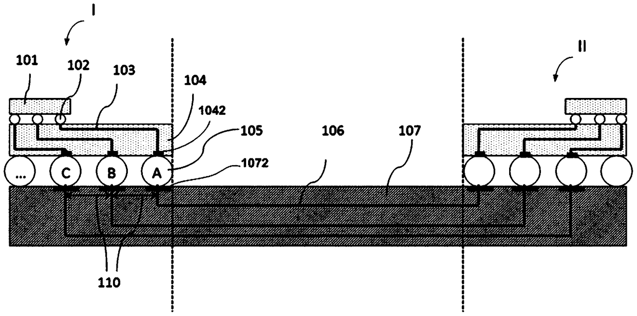
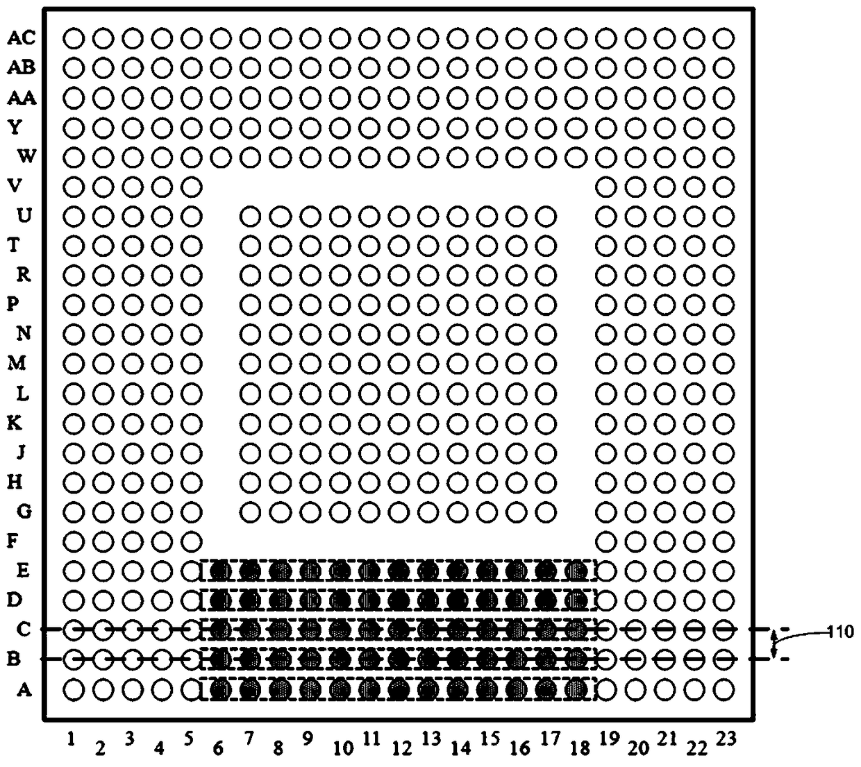
[0020] The embodiment of the present invention aims to provide a simple and efficient timing control method. The method adopted is to carry out group equal-length control according to the depth of signal arrangement on the substrate of the chip. Divide the solder joints of the same depth on the substrate into one group, and control the subst...


PUM


Abstract

The present invention provides an electronic device, which includes a carrier circuit board, and a chip loaded on the carrier circuit board. The chip includes a packaged substrate and a bare chip. The wiring of the substrate corresponding to the bonding point, the solder joints in the solder joint matrix at the bottom of the substrate include the first solder joint group and the second solder joint group respectively arranged along two parallel straight lines, and the first solder joint group and the second solder joint group The substrate traces connected to the solder joints are of equal length, and the substrate traces connected to the solder joints in the second solder joint group are of equal length, and the length difference between the two substrate traces is equal to the preset standard value. There are pads corresponding to the pads of the first pad group and the pads of the second pad group, and circuit board traces are connected to the pads, and the pads on the pads corresponding to the first pad group The length difference between the circuit board trace and the circuit board trace on the pad corresponding to the second pad group is equal to the preset standard value.

Description

technical field [0001] The embodiments of the present invention relate to chip technology, and in particular to a chip and an electronic device loaded with the chip. Background technique [0002] With the continuous development of integrated electronic technology, the operating frequency of the chip is getting higher and higher, and the requirements for the timing relationship of signals are becoming more and more stringent. For a high-speed transmission signal, such as a DDR (Double Data Rate, double rate) signal, the timing relationship directly affects the signal quality. If the chip input timing deviation in the board exceeds the design standard, the input command will not be executed. In order to ensure that the chip can work stably, the timing deviation between signals must be as small as possible. This requires chip designers to design circuits not only to achieve basic functions, but also to control the timing of signals as much as possible. The transmission of si...

Claims


Application Information

Patent Timeline
Patent Type & Authority Patents(China)
IPC IPC(8): H01L23/488H01L23/482H01L23/49
CPCH01L23/49816H01L23/49827H01L23/5381H01L24/13H01L24/16H01L2224/131H01L2224/16227H01L2224/81191H01L2924/15311H01L23/5386H01L2924/014H05K1/181H01L23/49811
Inventor 辛宇尘赵南王晨
Owner HUAWEI TECH CO LTD
Learn More