
Semiconductor packaging structure and forming method thereof, conductive jig and electroplating equipment

A packaging structure and semiconductor technology, applied in the direction of semiconductor devices, semiconductor/solid-state device manufacturing, semiconductor/solid-state device components, etc., can solve the problem of occupying the substrate area, and achieve the effect of improving integration and saving area

Active Publication Date: 2022-06-21
长电科技管理有限公司
View PDF11 Cites 0 Cited by
  • Summary
  • Abstract
  • Description
  • Claims
  • Application Information

AI Technical Summary

Problems solved by technology

The layout of these electroplated wires not only occupies the area of ​​the substrate, but also cannot judge the open and short circuit of the circuit by electrical measurement.

Method used


Image

  • Semiconductor packaging structure and forming method thereof, conductive jig and electroplating equipment
  • Semiconductor packaging structure and forming method thereof, conductive jig and electroplating equipment
  • Semiconductor packaging structure and forming method thereof, conductive jig and electroplating equipment

Examples


Embodiment Construction

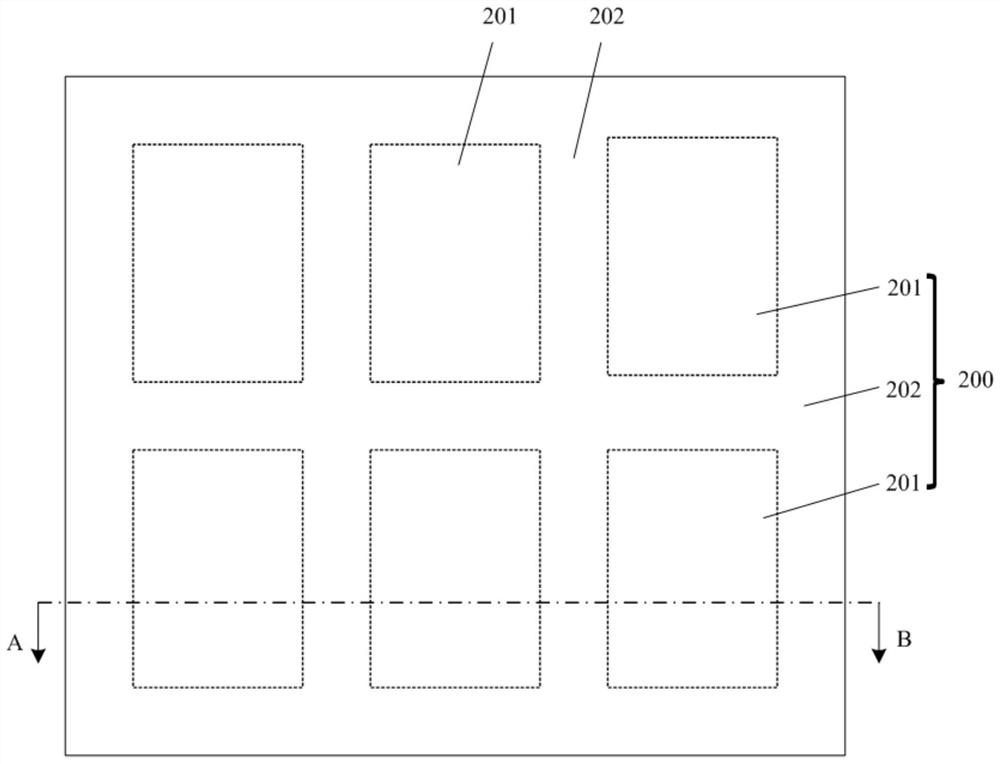
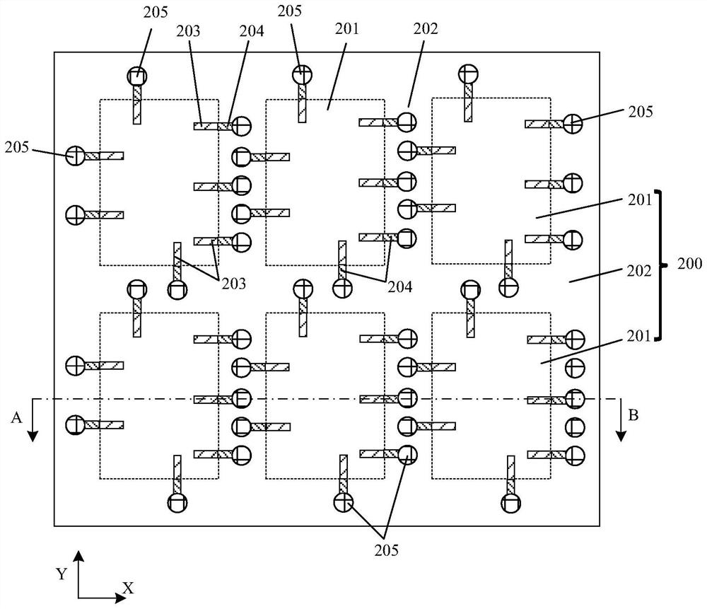
[0051] The specific embodiments of the present application will be described in detail below with reference to the accompanying drawings. When describing the embodiments of the present application in detail, for the convenience of description, the schematic diagrams are not partially enlarged according to the general scale, and the schematic diagrams are only examples, which should not limit the protection scope of the present application. In addition, the three-dimensional spatial dimensions of length, width and depth should be included in the actual production.

[0052] Some embodiments of the present application provide a method for forming a semiconductor package structure. The following describes the formation process of the semiconductor package structure in detail with reference to the accompanying drawings.

[0053] refer to figure 1 and figure 2 , figure 2 for figure 1 A schematic cross-sectional structure diagram along the cutting line AB direction, a substra...


PUM


Abstract

The invention discloses a semiconductor packaging structure and a forming method thereof, a conductive jig and electroplating equipment, and the forming method comprises the steps: a substrate, the front surface of the substrate comprises a plurality of discrete packaging regions and cutting channel regions which are located among the plurality of discrete packaging regions and surround each packaging region; a plurality of discrete metal lines located in each of the packaging areas; the plurality of discrete test welding pads are positioned in the cutting channel region around each packaging region, and each test welding pad is electrically connected with the corresponding metal circuit in each packaging region; and the plurality of discrete test welding pads are used for being electrically connected with a conductive jig when protective metal layers are electroplated on the surfaces of the plurality of discrete metal circuits, and the plurality of discrete metal circuits are electrically connected together through the conductive jig. According to the method, the electroplating of the metal circuit by the electroless lead is realized.

Description

technical field [0001] The present application relates to the field of semiconductor packaging, and in particular, to a semiconductor packaging structure and a method for forming the same, a conductive fixture and electroplating equipment. Background technique [0002] In the process of manufacturing integrated circuits, after the wafer is cut into a number of discrete chips, the chips are mounted on a substrate (or a substrate) or a lead frame to form a package structure with specific functions. [0003] In addition to fine lines, the substrate used in the aforementioned package structure also has many electrical contact pads (or I / O contacts, such as gold fingers, bonding pads for connecting bonding wires, and connecting bumps). bumppads, ball pads for connecting solder balls, etc.). These electrical contact pads are usually plated with a nickel-gold (Ni / Au) layer on the surface to ensure the stability of the electrical connection with the chip, or to protect the metal co...

Claims


Application Information

Patent Timeline
IPC IPC(8): H01L23/544H01L23/31H01L21/768H01L21/56H01L23/488
CPCH01L23/3107H01L24/13H01L21/56H01L21/76898H01L22/32H01L2224/13009
Inventor 缪富军杨志雷大勇刘烨
Owner 长电科技管理有限公司
Learn More