Vacuum transmission device
A vacuum transmission and vacuum technology, applied in the direction of transportation and packaging, conveyor objects, etc., to achieve the effect of improving the pass rate
- Summary
- Abstract
- Description
- Claims
- Application Information
AI Technical Summary
Problems solved by technology
Method used
Image
Examples
Embodiment 1
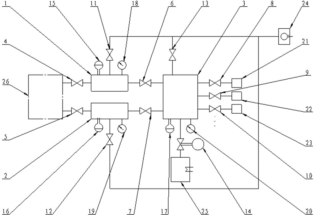
[0028] Such as figure 1 As shown, the vacuum transfer system (vacuum transfer platform) includes LoadLockA chamber 1, LoadLockB chamber 2 and vacuum transfer chamber 3, LLA plug-in gate valve 6 is set between LoadLockA chamber 1 and vacuum transfer chamber 3, and LLB plug-in The type gate valve 7 is arranged between the LoadLockB chamber 2 and the vacuum transfer chamber 3, and the vacuum transfer chamber 3 is equipped with different numbers of process chambers according to actual process requirements.
[0029] In this embodiment, three process chambers of process chamber A, process chamber B and process chamber C are installed, and the gate valve of process chamber A, gate valve of process chamber B and gate valve of process chamber C are respectively used to realize the connection with the vacuum transfer chamber 3. The communication and isolation among them; the atmospheric transmission system 26 realizes the communication and isolation between the LoadLockA chamber 1 and t...
Embodiment 2
[0034] Such as figure 1 As shown, the mechanical oil-free dry pump 24 is respectively connected to the LoadLockA chamber 1, the LoadLockB chamber 2 and the vacuum transmission chamber 3 through the pumping pipeline, and the pumping is turned on and off by the LLA rough pumping valve 11 and the LLB rough pumping valve 12 respectively. And vacuum chamber rough suction valve 13 control.
[0035]The mechanical oil-free dry pump 24 is used for LoadLockA chamber 1, LoadLockB chamber 2 and vacuum transmission chamber 3 to provide the fore-stage vacuum environment; the cryopump 25 is connected to the vacuum transmission chamber 3, and the high vacuum is controlled by the pneumatic slide valve 14 On-off of pumping; the cryopump 25 is used to provide a high vacuum environment for the vacuum transfer chamber 3, that is, to provide a vacuum environment for semiconductor vacuum transfer.
[0036] LLA vacuum gauge 15 is used to detect the vacuum degree of LoadLockA chamber 1; LLB vacuum ga...
Embodiment 3
[0042] Such as figure 2 As shown, the pure nitrogen gas source 34 supplies the LoadLockA chamber 1 , the LoadLockB chamber 2 and the vacuum transfer chamber 3 to supply nitrogen through the gas supply pipeline. A nitrogen main pipeline manual valve 32 is set on the nitrogen gas supply main line to control the on-off of nitrogen in the main pipeline; a pressure gauge 33 is installed on the main main line to detect the pressure of the nitrogen main pipeline.
[0043] The LLA fast-fill gas valve 27 and the LLA slow-charge gas valve 28 are installed on the LoadLockA chamber 1 to control the fast-fill nitrogen and slow-fill nitrogen of the LoadLockA chamber 1; the LLB fast-fill gas valve 29 and the LLB slow-charge gas valve 30 are installed on the On the LoadLockB chamber 2, control the fast nitrogen filling and slow nitrogen filling of the LoadLockB chamber 2; the vacuum chamber inflation valve 31 is installed on the vacuum transfer chamber 3, and controls the nitrogen gas chargi...
PUM
 Abstract
Description
Claims
Application Information
 - R&D
- Intellectual Property
- Life Sciences
- Materials
- Tech Scout
- Unparalleled Data Quality
- Higher Quality Content
- 60% Fewer Hallucinations
Browse by: Latest US Patents, China's latest patents, Technical Efficacy Thesaurus, Application Domain, Technology Topic, Popular Technical Reports.
© 2025 PatSnap. All rights reserved.Legal|Privacy policy|Modern Slavery Act Transparency Statement|Sitemap|About US| Contact US: help@patsnap.com


