
Time-domain temperature difference power supply system

A technology of power supply system and temperature difference power generation, which is applied in the direction of electrical components, generators/motors, etc., can solve the problems of not giving utilization and maintaining temperature difference, and achieve the effects of uniform distribution, reducing heat absorption efficiency, and enhancing heat exchange effect

Active Publication Date: 2016-07-27
复拓科学仪器(苏州)有限公司
View PDF14 Cites 5 Cited by
  • Summary
  • Abstract
  • Description
  • Claims
  • Application Information

AI Technical Summary

Problems solved by technology

[0005] However, this solution is only applicable to the temperature difference between the two surfaces of the power generation device at the same time, which can be converted into electrical energy. Obtain a constant temperature (or close to constant temperature) heat source or cold source to achieve continuous temperature difference with the other side to achieve the purpose of power generation
[0006] For the temperature difference in the time span that we often encounter in our daily life, the existing technology does not provide a solution for utilization, such as using the temperature difference between day and night endowed by nature, etc. (we refer to it as time domain temperature difference for short)

Method used


Image

  • Time-domain temperature difference power supply system
  • Time-domain temperature difference power supply system
  • Time-domain temperature difference power supply system

Examples


Embodiment Construction

[0044] The following will clearly and completely describe the technical solutions in the embodiments of the present invention with reference to the accompanying drawings in the embodiments of the present invention. Obviously, the described embodiments are only some, not all, embodiments of the present invention. Based on the embodiments of the present invention, all other embodiments obtained by persons of ordinary skill in the art without creative efforts fall within the protection scope of the present invention.

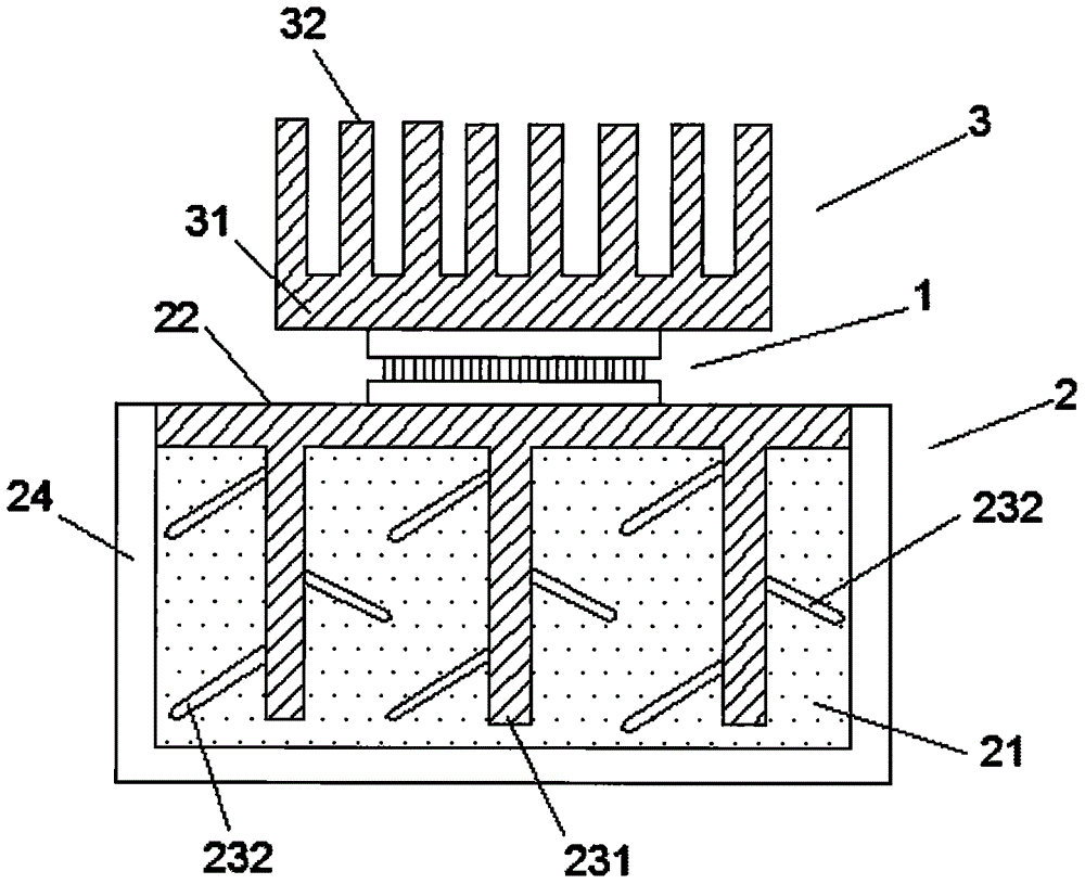
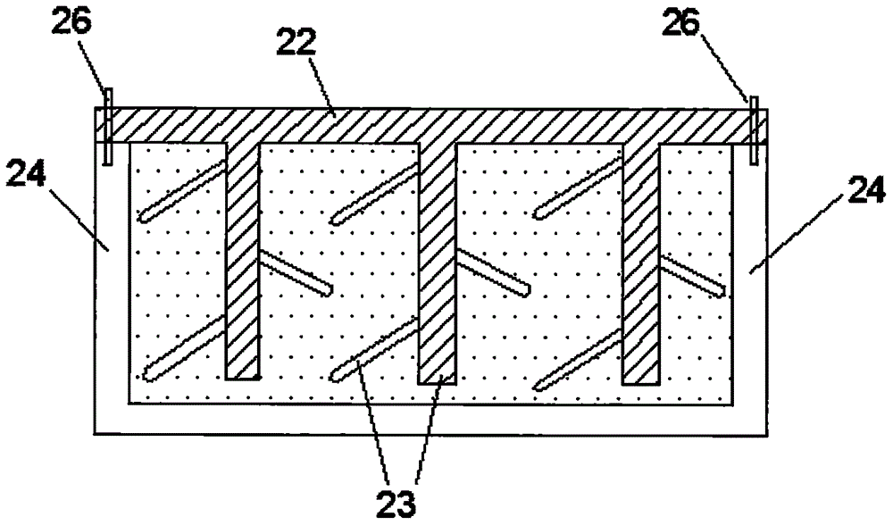
[0045] The present invention proposes a time-domain temperature difference power supply system, which combines figure 1 , figure 2 , including a thermoelectric power generation chip 1, a temperature storage body and a power supply terminal; the thermoelectric power generation chip includes a first surface 11 and a second surface 12; the first surface 11 of the thermoelectric power generation chip is close to the temperature storage body; The warm body contains a ...


PUM


Abstract

The invention provides a time-domain temperature difference power supply system. The time-domain temperature difference power supply system comprises a temperature difference power generation chip, a temperature storage body and a power supply end, wherein the temperature difference power generation chip comprises a first surface and a second surface, the first surface of the temperature difference power generation chip is in contact with the temperature storage body, the temperature storage body contains a substance with high specific heat, the temperature difference power generation chip is used for outputting generated electric energy to the power supply end, and a hot source of the temperature storage body is an environmental medium. With the change of temperature difference of the environmental medium, the temperature of a surface of the temperature difference power generation chip is constantly changed, the temperature change of the other surface of the temperature difference power generation chip is relatively delayed by the temperature storage body, and thus, the purpose that the temperature difference power generation chip works by means of the temperature of the environmental medium.

Description

technical field [0001] The present invention relates to the technical field of power generation systems, in particular to a system that utilizes time-domain temperature differences to enable thermoelectric power generation chips to supply power to loads and the like. Background technique [0002] The patent document with the publication number CN105048874A points out that in order to meet the needs of human life, more and more sensors need to be placed in inaccessible or harsh environments. The harsh environment of these areas determines that people cannot use chemical batteries to power wireless sensor nodes. , because it is often impossible to replace chemical batteries in these areas, so this document discloses a micro-thermoelectric generator with a simple structure that can use temperature difference to generate electricity. [0003] In addition, there are a large number of technologies for micro-energy collection using thermoelectric power generation devices, such as p...

Claims


Application Information

Patent Timeline
Patent Type & Authority Applications(China)
IPC IPC(8): H02N11/00
CPCH02N11/002
Inventor 王旭成
Owner 复拓科学仪器(苏州)有限公司
Learn More