Liquid cooling heat sink

A heat sink and liquid cooling technology, applied in the direction of semiconductor devices, electrical components, circuits, etc., can solve the problems of small space, unfavorable convective heat transfer, the heat sink should not be too large, and the heat transfer effect is reduced, so as to achieve simple structure and small volume , the effect of large heat dissipation

Inactive Publication Date: 2016-07-27
HENAN POLYTECHNIC UNIV
View PDF3 Cites 3 Cited by
  • Summary
  • Abstract
  • Description
  • Claims
  • Application Information

AI Technical Summary

Problems solved by technology

For example, air natural convection cooling has low cost, but low heat dissipation efficiency. In a working environment with limited volume, the heat sink of this kind of radiator should not be too large, and the small space is not conducive to convective heat transfer, so its heat transfer effect will be greatly reduced, thereby limiting its scope of use; while the heat pipe utilizes fluid principles such as capillary action, which has a good cooling effect, has extremely high thermal conductivity, good isothermal property, and the heat transfer area on both sides of the cold and hot sides can be It has the characteristics of arbitrary change, long-distance heat transfer, and temperature control, but the heat pipe is only applicable within a certain temperature range, and the relative cost is relatively high

Method used


Image

  • Liquid cooling heat sink
  • Liquid cooling heat sink
  • Liquid cooling heat sink

Examples


Embodiment Construction

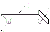
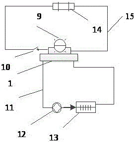
[0022] In order to make the purpose of the present invention, technical solutions and advantages clearer, the following will be combined with the attached image 3 , using a liquid cooling radiator of the present invention for high-power electronic components (such as high-power LEDs) will further describe the present invention in detail.

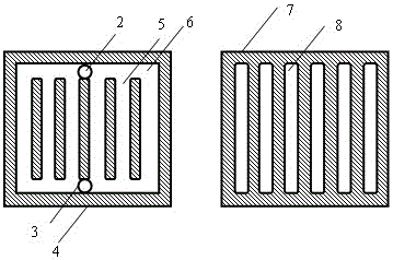
[0023] First, process the liquid-cooled radiator (1): Take two copper blocks of 100mm×100mm and thickness of 19mm as the processing objects, and process the liquid-cooled radiator according to the following steps: select two pieces with good thermal conductivity and have a certain thickness The metal plates a (4) and b (7); process the metal plate a (4) at a certain distance along the boundary to form a groove space (6) that communicates with each other and has multiple parallel passages (5) in the middle; (7) Process some parallel grooves, the positions of these parallel grooves (8) correspond to the parallel channels (5) processed in the ...


PUM


Abstract

The invention relates to the technical field of cooling of a high-power component, in particular to a liquid cooling heat sink employing a liquid heat conduction medium to dissipate heat. The liquid cooling heat sink is characterized in that a heat sink (1) is formed by welding a metal plate a (4) and a metal plate b (7), wherein the metal plate a (4) is provided with a liquid inlet (2) and a liquid outlet (3), parallel passages (5) are arranged on the inner side of the metal plate a (4) and are communicated with one another to form a groove space (6), and parallel grooves (8) are formed in the inner side of the metal plate b (7) and are not communicated with one another. In the liquid cooling heat sink disclosed by the invention, the surface, in contact with a hot source, of the heat sink and a cooling surface are both horizontal smooth plane so as to fully expand a heat exchange area, and the internal passage of a liquid cooling cavity is designed to a snake shape to reduce the flow resistance of a liquid in a water cooling cavity. The material of the liquid cooling heat sink shall be selected from metal with favorable heat conduction performance, such as copper and aluminum. In the liquid cooling heat sink, on one side, opposite to the liquid inlet (2) and the liquid outlet (3), of the cooling surface, a heating component is pasted on the cooling surface by heat conduction silica gel.

Description

technical field [0001] The invention relates to the technical field of heat dissipation of high-power electronic components, in particular to a liquid-cooled radiator that utilizes a liquid heat-conducting working fluid to dissipate heat. Background technique [0002] For semiconductor electronic components such as high-power LEDs, heat will be generated after power-on, and semiconductor components have their normal operating temperature range. If they work at high temperatures for a long time, they will cause irreversible functional decline, so they must be dissipated. Traditional heat dissipation methods include air natural convection cooling, forced air cooling and liquid cooling. Since the emergence of heat pipes, heat pipes have appeared for heat dissipation. For example, air natural convection cooling has low cost, but low heat dissipation efficiency. In a working environment with limited volume, the heat sink of this kind of radiator should not be too large, and the s...

Claims


Application Information

Patent Timeline
IPC IPC(8): H01L33/64
CPCH01L33/648
Inventor 王华张刘钢朱崎峰陈小砖孙志君
Owner HENAN POLYTECHNIC UNIV
Why Eureka
Try Eureka