
A Fatigue Test Device for Anti-Icing Main Blade

A technology for fatigue testing and main blades, which is applied in the direction of measuring devices, testing of mechanical components, testing of machine/structural components, etc. It can solve problems such as flapping moment, shimmy bending moment and torque difficulties, and achieve compact structure, The effect of high loading accuracy and fast frequency

Active Publication Date: 2019-06-25
CHINA HELICOPTER RES & DEV INST
View PDF9 Cites 0 Cited by
  • Summary
  • Abstract
  • Description
  • Claims
  • Application Information

AI Technical Summary

Problems solved by technology

[0003] In the prior art, it is difficult to simultaneously apply flapping moment, shimmy bending moment and torque to the anti-icing main blade test piece due to the long middle area to be assessed.
For example, in the Chinese patent application with the application number 201210570656.8, a device for applying equal bending moments in the assessment area is proposed, using an actuator to apply the same bending moment. For example, in the Chinese patent application with the application number 201410727507.7, a A bending moment loading mechanism such as an anti-deicing main blade implements a bending moment to the anti-deicing main blade, but cannot apply a torque load. Simultaneous application of flapping moment, shimmy moment and torque loads for main blade fatigue testing

Method used


Image

  • A Fatigue Test Device for Anti-Icing Main Blade
  • A Fatigue Test Device for Anti-Icing Main Blade

Examples


Embodiment 1

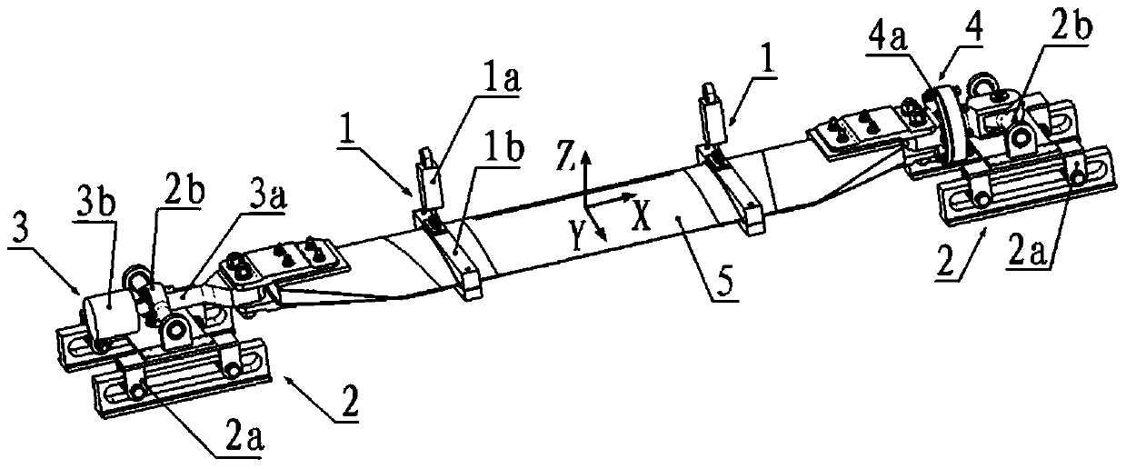
[0030] like figure 1 As shown, in this embodiment, the two ends of the test piece 5 are connected to the support platform 2 by two different devices. In the illustration, the test piece 5 is the main blade, with its center as the origin, The long side is taken as the X axis, the upward direction is the Z axis, and the direction perpendicular to the X and Z axes is the Y axis. It is a schematic illustration of the anti-icing main blade fatigue test device.

[0031] refer to figure 1 , the two bending moment application assemblies 1 are symmetrically distributed left and right in the X-axis direction, and are respectively arranged on the test piece 5 from the center to the two ends, and the two bending moment application assemblies 1 are connected to the test piece 5 The center is the same distance. Each bending moment application assembly 1 includes a set of linear actuator 1a and clamping mechanism 1b. The connection between the linear actuator 1a and the clamping mechanism ...

Embodiment 2

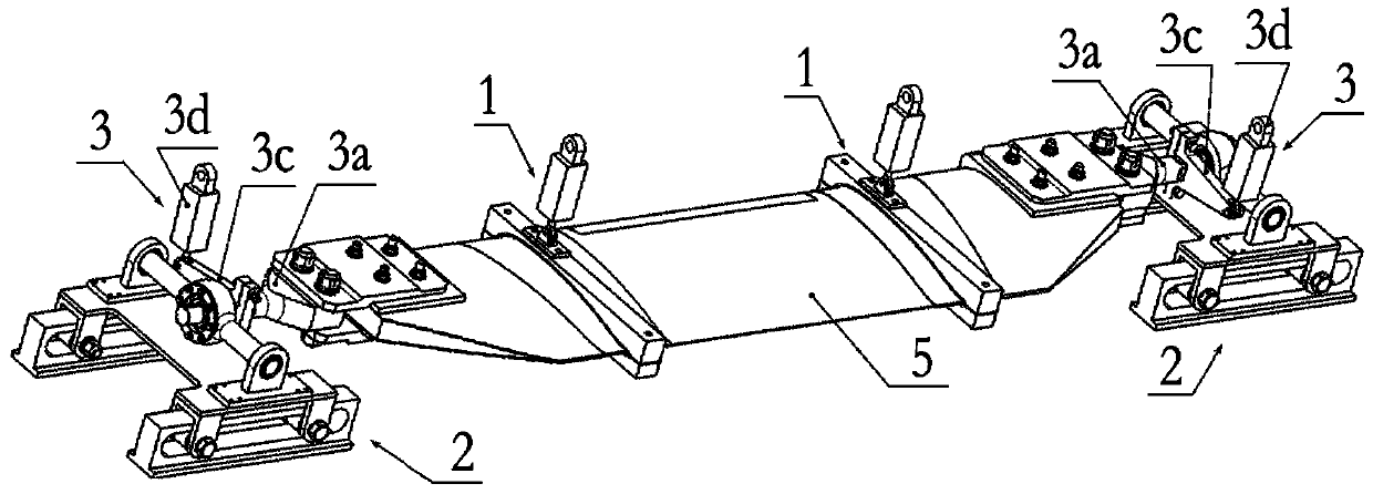
[0039] Similar to Example 1, the difference is that when the stiffness of the test piece 5 is not large enough, and the torque cannot be smoothly transmitted from one end of the test piece 5 to the other end under the condition of bending deformation, two support platforms 2 can be selected A test program in which the torque application assembly 3 is installed. That is, in this embodiment, if figure 2 As shown, the connecting component is a torque applying component 3, that is, both ends of the test piece 5 are connected to the support platform 2 through the torque applying component 3. This solution adjusts the flapping moment and shimmy bending moment by controlling the installation angle of the rotating shaft 3a The proportional relationship, loading control is more difficult.


PUM


Abstract

The invention relates to an anti-icing and deicing main blade fatigue test device, and belongs to the technical field of helicopter blade fatigue tests.The device comprises two bending moment applying assemblies, two supporting platforms, a torque moment applying assembly, a connecting assembly and a test piece; one end of the test piece is connected with one supporting platform through the torque moment applying assembly, and the other end of the test piece is connected with the other supporting platform through the connecting assembly; one end of each bending moment applying assembly is arranged on the test piece and extends outwards to form the other end capable of applying bending moment; one end of the torque moment applying assembly is fixed to the test piece and extends outwards to form the other end capable of loading torque moment, and a rotating shaft is arranged between the two ends of the torque moment applying assembly and rotatably arranged on the corresponding supporting platform.Through the device, bending moment applying and torque moment applying can be simultaneously achieved and also can be implemented independently, and the requirements of an anti-icing and deicing main blade fatigue test are met.

Description

technical field [0001] The invention belongs to the technical field of helicopter blade fatigue tests, in particular to an anti-deicing main blade fatigue test device. Background technique [0002] The anti-deicing main blade fatigue test is an important test content in the helicopter blade fatigue test technology, which has important guiding significance for the life and safety of the helicopter blade. The anti-icing main blade fatigue test needs to be applied in the entire assessment area The loads are: flapping moment, shimmy moment and torque. [0003] In the prior art, it is difficult to simultaneously apply the flapping moment, shimmy bending moment and torque to the anti-icing main blade test piece due to the long middle area to be assessed. For example, in the Chinese patent application with the application number 201210570656.8, a device for applying equal bending moments in the assessment area is proposed, using an actuator to apply the same bending moment. For ex...

Claims


Application Information

Patent Timeline
Patent Type & Authority Patents(China)
IPC IPC(8): G01M13/00
CPCG01M13/00
Inventor 刘炉山夏树立潭峰
Owner CHINA HELICOPTER RES & DEV INST
Learn More