
A hydraulic pipe joint vibration test device

A technology for hydraulic pipe joints and vibration testing, which is applied in vibration testing, measuring devices, and testing of machine/structural components. smooth effect

Active Publication Date: 2019-06-25
苏强格液压(湖北)有限公司
View PDF7 Cites 0 Cited by
  • Summary
  • Abstract
  • Description
  • Claims
  • Application Information

AI Technical Summary

Problems solved by technology

However, both of these two methods require a large operating space, and the generation of motion is directly driven by the motor, which has high requirements on the motor.

Method used


Image

  • A hydraulic pipe joint vibration test device
  • A hydraulic pipe joint vibration test device

Examples


Embodiment Construction

[0011] Below in conjunction with accompanying drawing and embodiment the patent of the present invention is further described.

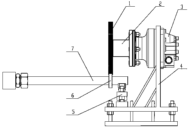
[0012] Such as figure 1 As shown, a hydraulic pipe joint vibration test device includes a multi-cam disc (1), a fixed flange (2), a hydraulic motor (3), a base support (4), a spring structure support (5), a deep groove ball The bearing (6) and the tested piece (7) are characterized in that: the multi-cam disc (1) is fixed on the fixed flange (2) by standard bolts, and the fixed flange (2) is connected by standard bolts On the hydraulic motor (3), the hydraulic motor (3) is fixedly sleeved on the base bracket (4) through standard bolts, and the spring structure bracket (5) is fixed on the base bracket (4) through standard bolts, The deep groove ball bearing (6) is fixed on the steel pipe of the test piece (7) through interference fit, and the multi-cam disc (1) keeps in conflict with the deep groove ball bearing (6).

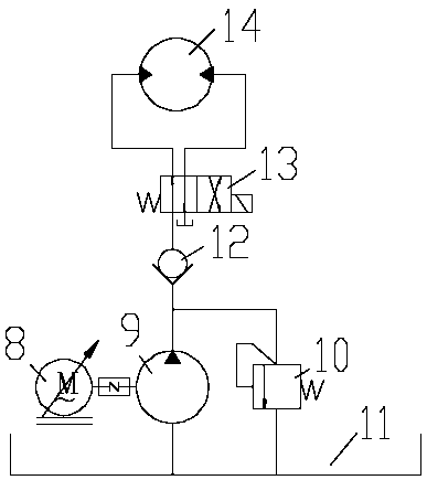
[0013] Such as figure 2 show...


PUM


Abstract

The invention provides a hydraulic pipe joint vibration test device which comprises a multi-cam disc, a fixed flange, a special hydraulic motor, a base bracket, a spring structure bracket, a deep groove ball bearing and a tested piece. The geometrical shape of the multi-cam disc is the synthesis of a sinusoidal curve and a circle. The fixed flange connected with the hydraulic motor rotates at the required rotational speed and acts on the deep groove ball bearing with the shape of a cam, and the vibration of the tested piece is realized. The hydraulic pipe joint vibration test device provided by the invention is suitable for the vibration test of a hydraulic pipe joint, is suitable for the low-speed and stable vibration requirement, and has the characteristics of compact structure, low noise and high practicability.

Description

technical field [0001] The invention relates to a hydraulic pipe joint test method, in particular to a hydraulic pipe joint vibration test device. Background technique [0002] According to the requirements of the vibration test in the national standard GB / T 26143-2010 "Test methods for hydraulic pipe joints", a device that can provide rotation or in-plane vibration with a vibration frequency of 10-50 Hz is required. Existing vibration generation methods include mechanical, electric and electro-hydraulic. Since this test does not require high vibration frequency, it is not suitable to use high-cost electro-hydraulic or electro-hydraulic. Existing mechanical vibration tables include direct drive type and centrifugal type. The direct drive type includes a crank linkage mechanism, crank slider mechanism and cam ejector mechanism; the centrifugal type requires a pair of meshing gears. However, both of these two methods require a large operating space, and the movement is direc...

Claims


Application Information

Patent Timeline
Patent Type & Authority Patents(China)
IPC IPC(8): G01M7/02
CPCG01M7/02
Inventor 杨孟林金侠杰缪正成倪晓春
Owner 苏强格液压(湖北)有限公司
Learn More