
High-speed testing machine for offset double oscillating follower double swash plate end face cam joint bearing

An end cam and spherical plain bearing technology, applied in the direction of mechanical bearing testing, etc., can solve the problems of inability to meet the fatigue test of high-frequency swinging aeronautical spherical plain bearings, restricting the development of high-frequency swinging aeronautical spherical plain bearings, and dynamic balance of difficult-to-move components, so as to achieve wear and tear. Light, low friction, low impact effect

Inactive Publication Date: 2015-10-14
YANSHAN UNIV
View PDF7 Cites 0 Cited by
  • Summary
  • Abstract
  • Description
  • Claims
  • Application Information

AI Technical Summary

Problems solved by technology

The oscillating frequency of joint bearings on some aviation vehicles is very high (30-70Hz), and the joint bearing fatigue testing machines currently used in my country mostly use crank slider mechanisms. Because this mechanism is difficult to achieve dynamic balance of moving components, the highest oscillating frequency Generally, it does not exceed 20Hz, which cannot meet the fatigue test requirements of high-frequency oscillating aviation joint bearings, which seriously restricts the development of domestic high-frequency oscillating aviation joint bearings.

Method used


Image

  • High-speed testing machine for offset double oscillating follower double swash plate end face cam joint bearing
  • High-speed testing machine for offset double oscillating follower double swash plate end face cam joint bearing
  • High-speed testing machine for offset double oscillating follower double swash plate end face cam joint bearing

Examples


Embodiment

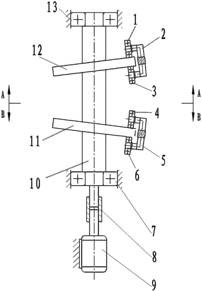
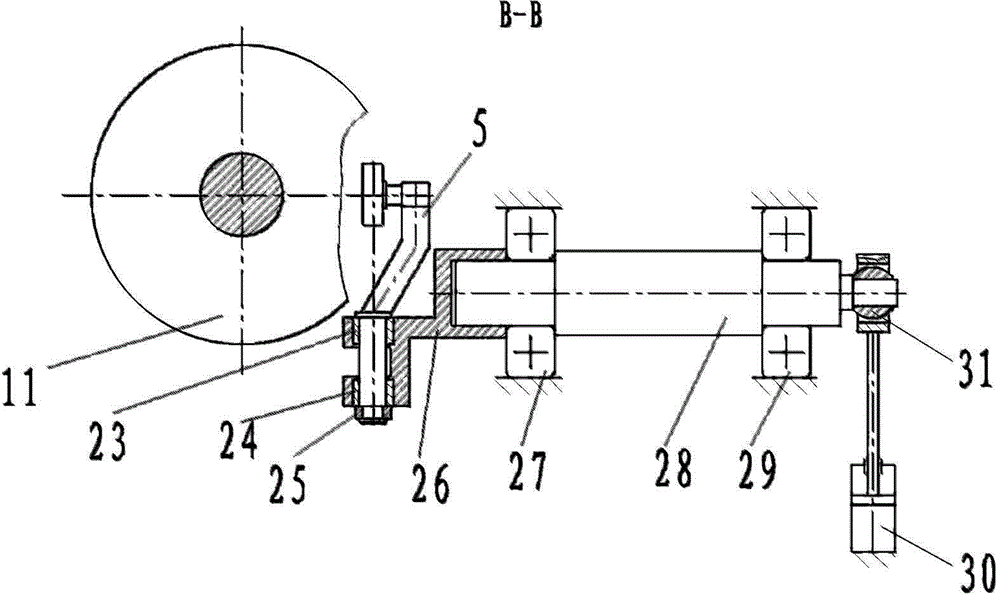
[0018] exist Figure 1 ~ Figure 3 Shown is a schematic diagram of the working state of a high-speed testing machine for offset double sway followers double swash plate end face cam joint bearings. One end of the high-speed rotating shaft 10 supported on two rolling bearings V and VI (7, 13) passes through The shaft device 8 is connected with the motor 9 (or hydraulic motor), and two swash plate end cams I, II (11, 12) are fixedly connected to the high-speed rotating shaft 10, and the two swash plate end cams I, II (11, 12 ) is symmetrical with respect to the plane that passes through the middle plane of each swash plate end face cam and the line connecting the two intersection points of the high-speed rotating shaft 10 axis and is perpendicular to the high-speed rotating shaft 10 axis, and each swash plate end face cam I, II (11, 12 ) The angle between the normal of the middle plane and the axis of the high-speed rotating shaft 10 is 15°. The high-frequency swing shaft I17 is...


PUM


Abstract

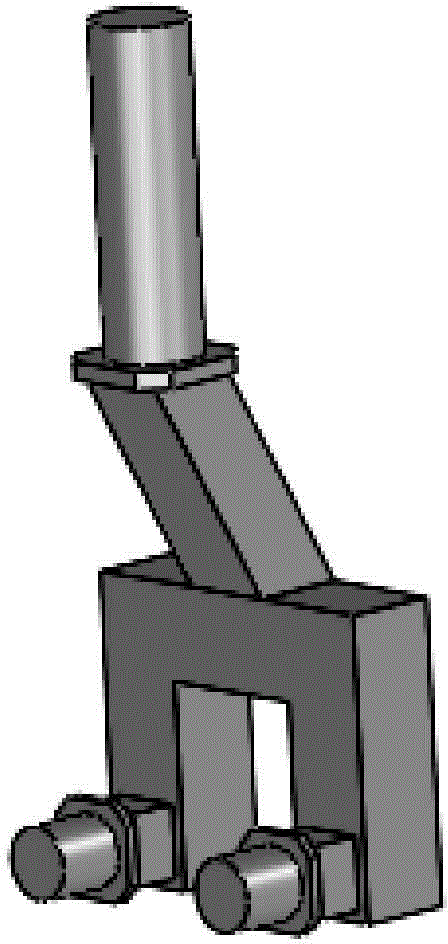
The invention discloses an offset double-oscillating-follower double-swash-plate-end-cam knuckle bearing high-speed testing machine. A swash plate end cam I and a swash plate end cam II are fixedly connected on a high-speed rotary shaft, one end of a high-frequency oscillating shaft I is fixedly connected with an inner ring of a testing knuckle bearing I, an outer ring of the testing knuckle bearing I is fixedly connected with a loading hydraulic cylinder I, the other end of the high-frequency oscillating shaft I is fixedly connected with an L-shaped support I, and a C-shaped oscillating shaft I is arranged in bearing holes of the L-shaped support I through a sliding bearing I and a sliding bearing II. A rolling bearing I and a rolling bearing II are arranged on each short cross shaft on the lowest end of the C-shaped oscillating shaft I, and the rolling bearing I and the rolling bearing II are tangent with the end face of the swash plate end cam I respectively. The high-speed rotary shaft and the two swash plate end cams are of a dynamic balancing structure, the swash plate end cams and the rolling bearings contacting the swash plate end cams generate rolling friction, the friction is small, abrasion is less, and noise is low. The oscillating frequency can be 70-80 Hz and can meet requirements for high-frequency oscillating aviation knuckle bearing fatigue testing.

Description

technical field [0001] The invention relates to a high-speed testing machine for an offset double swing follower double swash plate end face cam joint bearing. Background technique [0002] Spherical joint bearing is a kind of sliding bearing with special structure, which is mainly composed of an inner ring with an outer spherical surface and an outer ring with an inner spherical surface. Joint bearings are widely used in the connection of swing components of aviation vehicles because of their flexible rotation, maintenance-free, compact structure, easy assembly and disassembly, large load-carrying capacity, and long life. [0003] During the flight of an aircraft, the failure of any component will cause catastrophic consequences. Therefore, it is a very serious and important work to determine the service life of the components of the aircraft. In order to accurately determine the service life of the components of the aircraft, the usual practice is to carry out fatigue te...

Claims


Application Information

Patent Timeline
Patent Type & Authority Patents(China)
IPC IPC(8): G01M13/04
Inventor 刘喜平杨育林黄世军
Owner YANSHAN UNIV
Learn More