Welding fixture

A welding jig and fixture technology, applied in welding equipment, auxiliary welding equipment, welding/cutting auxiliary equipment, etc., can solve the problems of manual and machine not being able to cooperate well, single direction of welding positioning and tightening, and welding seam damage, etc. Improve welding efficiency and the effect of low automation, proficiency and operational technical requirements, reducing the impact of welding quality

Active Publication Date: 2018-06-12
ANHUI HAODING METAL PROD LIMITED
View PDF5 Cites 0 Cited by
  • Summary
  • Abstract
  • Description
  • Claims
  • Application Information

AI Technical Summary

Problems solved by technology

However, in the direction of the welding surface, due to thermal expansion and tangential loads, thermal stress along the welding surface is generated, which may lead to widening of the weld seam and welding deformation, so a load should also be added to the direction of the welding surface
And after one side is welded, it is often necessary to manually turn over the welding fixture and the weldment as a whole. This turning process is slow and cumbersome, and it is easy to damage the weld, affecting the welding quality, and the production efficiency is low.
[0003] At present, the welding fixture for double-sided sheets generally includes a support base, a support plate, a limit device, a hinge positioning system, and a power device. The positioning device is bulky and comprehensive, but its positioning and tightening direction for welding is single, and there is no clamp along the welding surface. tension
Or include devices such as a base, a reversible clamp body, a reed clamp, a reversing handle, and a reversing shaft. This device is lighter than the traditional double-sided clamp and is easy to flip, but it needs to be operated manually, which requires a certain degree of technical proficiency for the operator. Requirements, and long-term work is prone to fatigue, and manual and machine cannot cooperate well in automated production, which affects production efficiency

Method used


Image

  • Welding fixture
  • Welding fixture

Examples


Embodiment Construction

[0013] The technical solution of the present invention will be further described below in conjunction with the accompanying drawings.

[0014] The present application relates to a welding jig, which is used for double-sided welding of plates.

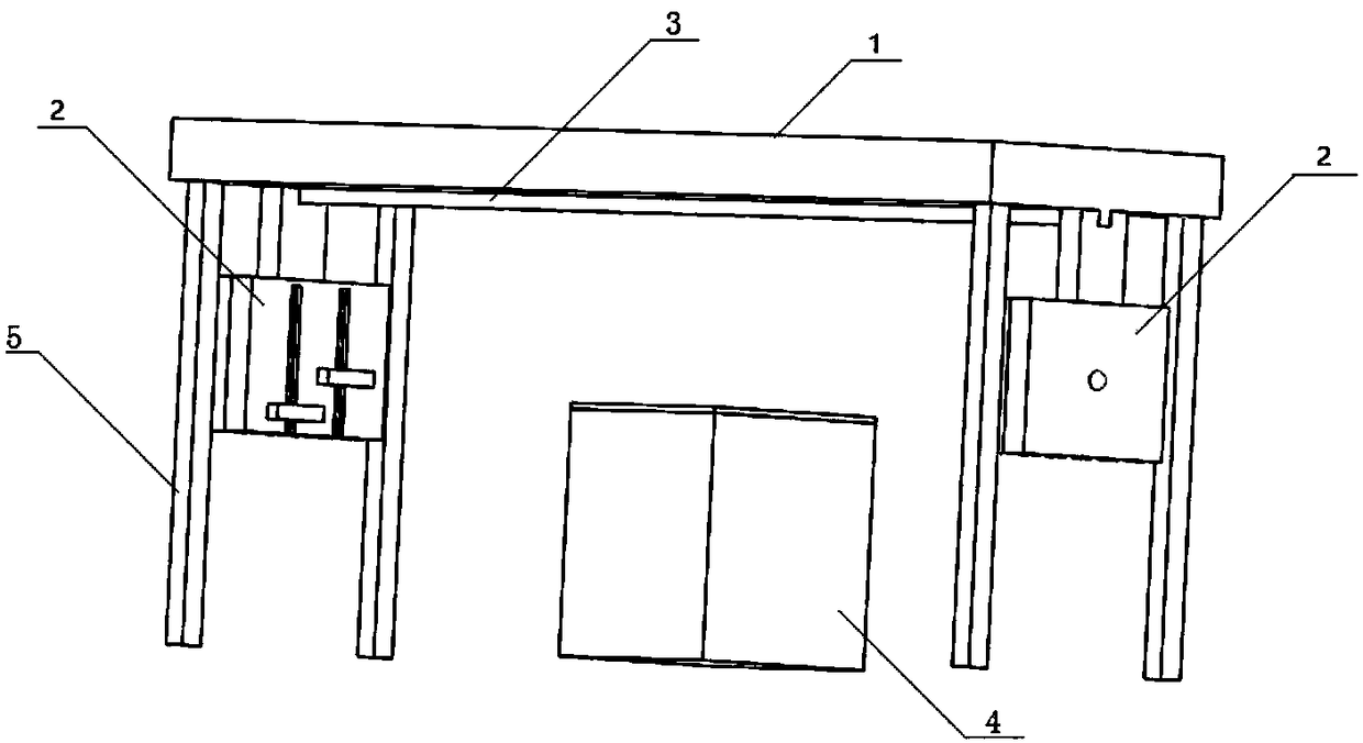
[0015] Such as figure 1 and figure 2 As shown, the welding fixture includes a workbench base 1, a double-sided welding combination splint 2 connected to the workbench base 1, a slide rail 3, a welding operation table 4 for placing weldments, and a welding table 4 connected to the workbench base 1. Bracket 5, the front clamp rotating plate 7 and the rear clamp rotating plate 8 that are connected by the rotating shaft and can rotate clockwise or counterclockwise around the rotating shaft, the slidable clamps 9, sliding grooves 10 and movable clamps positioned on both sides of the front clamp rotating plate 7 Lifting support rod 11.

[0016] The double-sided welding combination splint 2 is also connected with a motor, the double-sided ...


PUM


Abstract

The invention relates to a welding fixture. The welding fixture comprises a workbench base, double-side welding combined clamping plates and sliding rails which are connected to the workbench base, a welding operating table used for placement of a weldment, brackets connected to the workbench base, a front fixture rotating plate and a rear fixture rotating plate which are connected via a rotating shaft and can rotate around the rotating shaft clockwise or anticlockwise, and slideable fixtures, sliding grooves and liftable supporting rods which are positioned on two sides of the front fixture rotating plate. According to the invention, the automaton of welding turnover is realized through rotation of the double-side welding combined clamping plates, the influence on the welding quality due to turnover originally is reduced, the operation of workers is simplified, only few manual operation is needed, requirements for the degree of proficiency and operating techniques are lower, the quality of welding products is guaranteed, and the welding efficiency and automation degree of double-side welding are improved.

Description

technical field [0001] The invention relates to a welding jig, in particular to a double-sided welding combined welding jig. Background technique [0002] In China, double-sided welding is used for the welding of large thick plates. After welding on the first side, welding is performed on the back of the workpiece. Since the weldment is large and thick, a tangential load should be applied during welding so that the weldment will not be deformed due to the heat of the weld. For this, a clamp parallel to the welding surface is generally added to fix the weldment. However, in the direction of the welding surface, due to thermal expansion and tangential loads, thermal stress along the welding surface is generated, which may cause the weld to widen and weld deformation, so a load should also be added to the direction of the welding surface. And after one side is welded, it is often necessary to manually turn over the welding fixture and the weldment as a whole. This turning proc...

Claims


Application Information

Patent Timeline
Patent Type & Authority Patents(China)
IPC IPC(8): B23K37/04B23K37/047
CPCB23K37/0435B23K37/047
Inventor 周健刘庚周倩高川云谢宇杰
Owner ANHUI HAODING METAL PROD LIMITED
Why Eureka
Try Eureka