


Quick Research
Generate reliable direction feasibility study reports for your R&D in just a few steps.

Technical Q&A
Discover and master advanced knowledge NOW. Basics, ideas, possibilities, all at once.

Find Solutions
As an expert in R&D theories, this can generate solutions to your technical problems instantly.

Evaluate Feasibility
Analyze your overall solution with one click, know your potential R&D risks in advance.

Monitor Landscape
Get weekly tech updates, stay abreast of the latest tech innovations and key insights.
Angular contact ball bearings
An angular contact ball bearing, axial technology, applied in the direction of shafts and bearings, bearing elements, roller bearings, etc., can solve the problems of size increase and area increase in the height direction, and achieve large preload load, increased bearing capacity, The effect of increasing the contact angle
- Summary
- Abstract
- Description
- Claims
- Application Information
AI Technical Summary
Problems solved by technology
Method used
Image

Examples
no. 2 approach
[0124] Figure 7 A double row angular contact ball bearing 1a according to a second embodiment of the present invention is shown. In addition, the same code|symbol is attached|subjected to the same or equivalent part as 1st Embodiment, and description is abbreviate|omitted or simplified.
[0125] Such as Figure 7 As shown, in this embodiment, in consideration of the assemblability to a mechanical device, it is a double row angular contact ball bearing arranged in combination on the back, which has: a single outer ring 10a having a pair of outer ring raceway surfaces 11, 11; A pair of inner rings 20, 20 with inner ring raceway surfaces 21, 21; a plurality of balls 3 arranged in double rows between the pair of outer ring raceway surfaces 11, 11 and the pair of inner ring raceway surfaces 21, 21; And the cage 30 of the ball guide type having a plurality of pockets 34 holding a plurality of balls 3 respectively. A flange portion 14 for fixing is provided on the outer ring 10 a...
no. 3 approach
[0130] Figure 9 (a) and (b) show the double row angular contact ball bearing 1b concerning 3rd Embodiment of this invention. In addition, the same code|symbol is attached|subjected to the same or equivalent part as 1st Embodiment, and description is abbreviate|omitted or simplified.
[0131] Such as Figure 9 As shown in (a), in this embodiment, it is a double-row angular contact ball bearing 1b arranged in frontal combination, including: a pair of outer rings 10 respectively having outer ring raceway surfaces 11, 11; a pair of inner rings A single inner ring 20a on raceway surfaces 21, 21; a plurality of balls 3 arranged in double rows between a pair of outer ring raceway surfaces 11, 11 and a pair of inner ring raceway surfaces 21, 21; The cage 30 is a ball guide type cage 30 with a plurality of pockets 34 for the balls 3 .
[0132] In this case, the outer rings 10 , 10 are disassembled and the outer rings 10 , 10 are adjusted and polished in order to adjust the preload ...
Embodiment 1
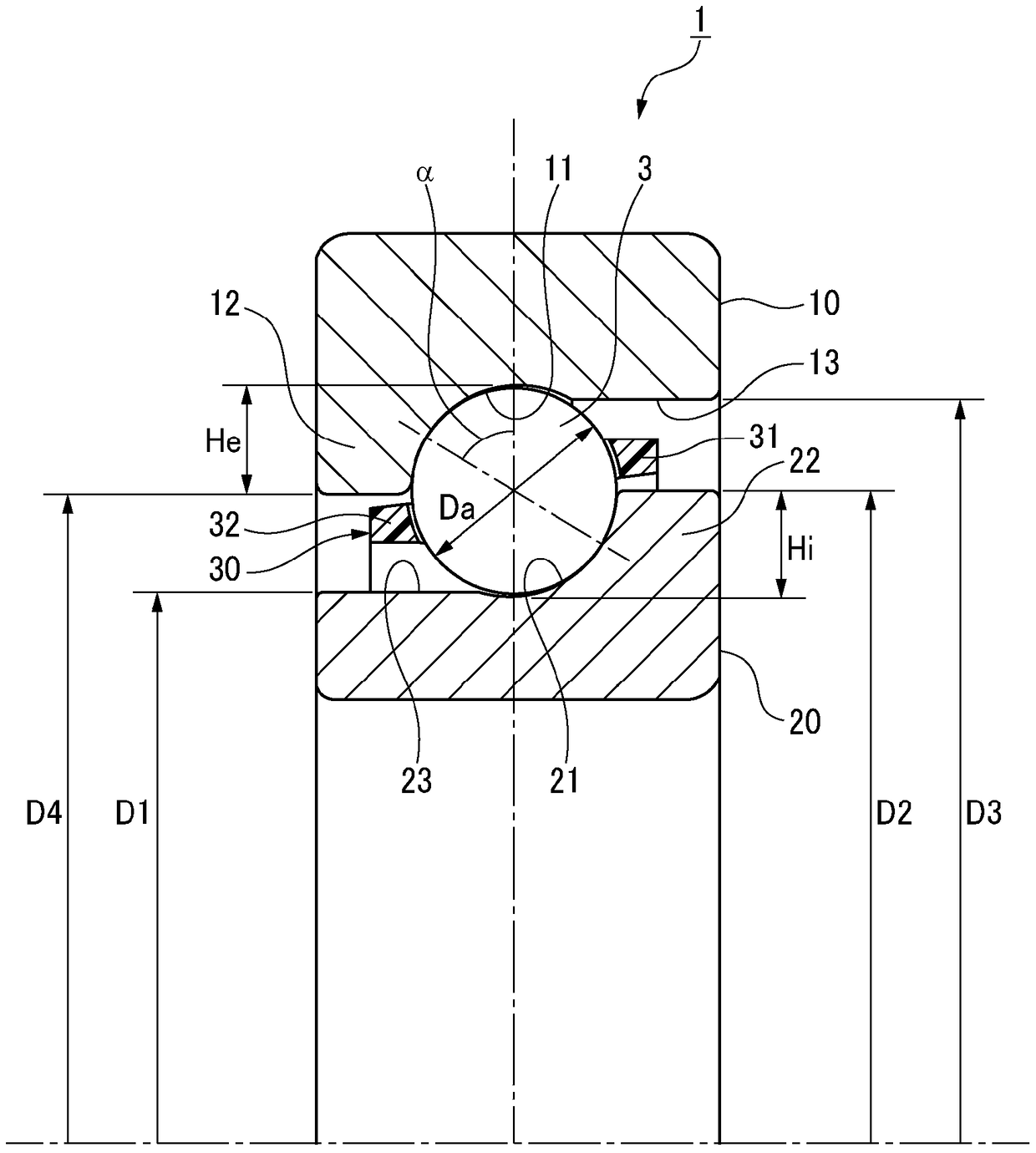
[0138] Figure 10 Example 1 of the angular contact ball bearing for supporting a ball screw in which the outer ring of the second embodiment is integrated and the inner ring is divided into two is shown. In this case, various specifications and dimensions of the angular contact ball bearing are set as follows.
[0139] Contact angle α: 50°
[0140] Ball diameter Da: 6.35mm
[0141] Ae (=radial height He / ball diameter Da of outer ring groove shoulder): 0.38
[0142] Ai (=radial height Hi / ball diameter Da of inner ring groove shoulder): 0.38
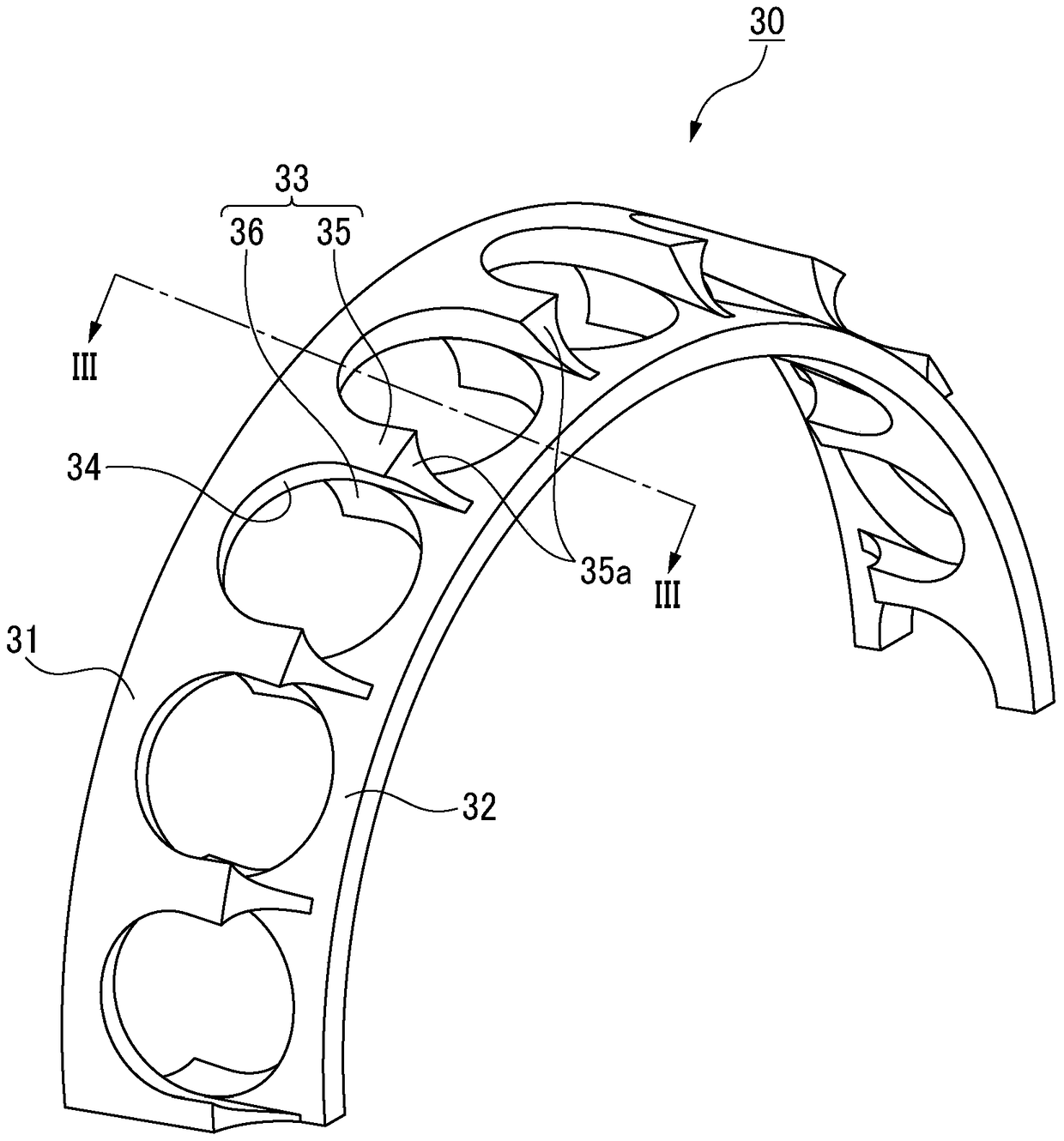
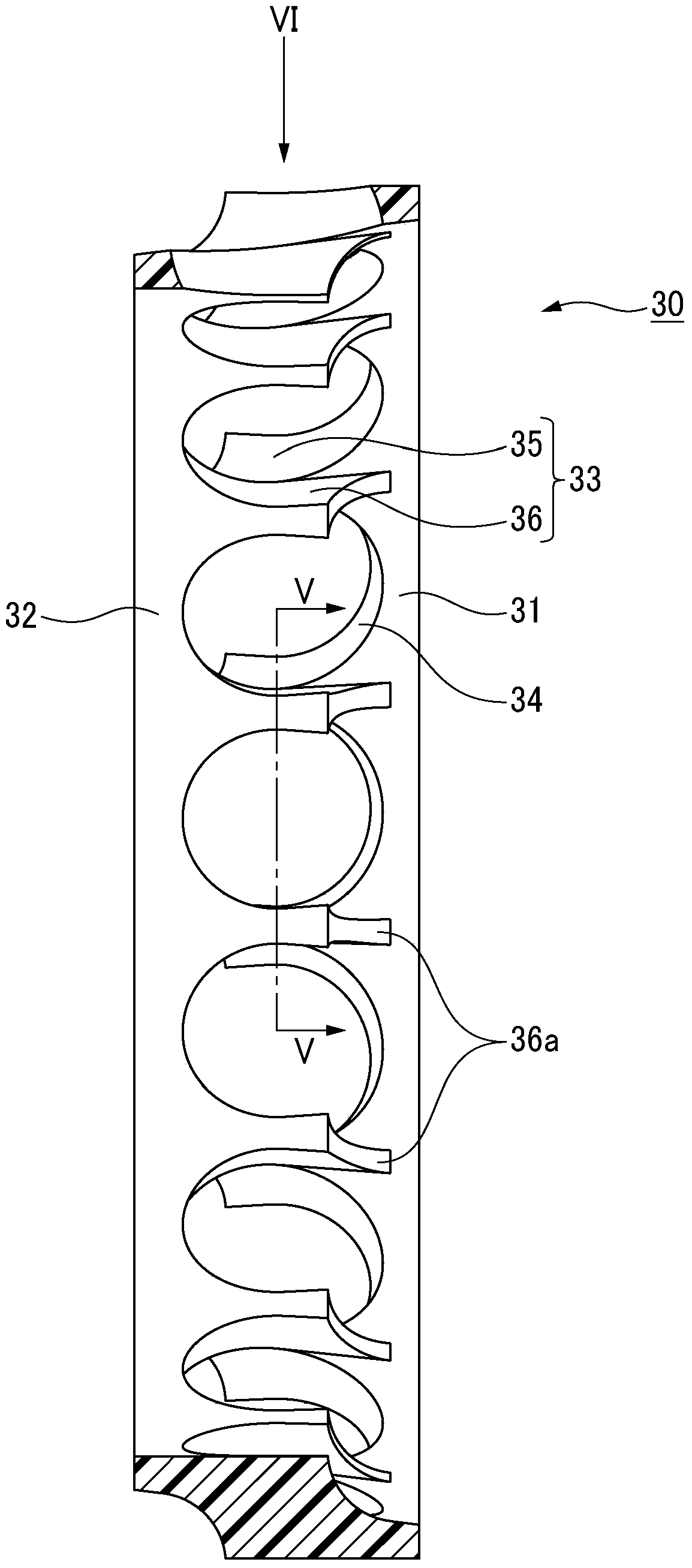
[0143] Cage material: polyamide resin
[0144] Radius R1 of curvature of the axial side surface 35a of the outer diameter side column portion 35: 0.27×Da (1.7mm)
[0145] Radius R2 of curvature of axial side surface 36a of inner diameter side column portion 36: 0.27×Da (1.7mm)
[0146] Outer diameter side pocket diameter φDo: 0.80×Da (5.08mm)
[0147] Inner diameter side pocket diameter φDi: 0.80×Da (5.08mm)
PUM
 Abstract
Description
Claims
Application Information
 - R&D Engineer
- R&D Manager
- IP Professional
- Industry Leading Data Capabilities
- Powerful AI technology
- Patent DNA Extraction
Browse by: Latest US Patents, China's latest patents, Technical Efficacy Thesaurus, Application Domain, Technology Topic, Popular Technical Reports.
© 2024 PatSnap. All rights reserved.Legal|Privacy policy|Modern Slavery Act Transparency Statement|Sitemap|About US| Contact US: help@patsnap.com