
New energy electric vehicle waste heat energy storage type air-conditioning system based on solution dehumidification and method thereof

A solution dehumidification, electric vehicle technology, applied in vehicle components, air handling equipment, heating/cooling equipment, etc., can solve the problems of poor heat dissipation stability of battery packs, endangering vehicle safety, and low energy utilization rate, and achieve improved heat dissipation effect, The effect of reducing temperature control load and long service life

Active Publication Date: 2016-07-20
ZHEJIANG UNIV
View PDF3 Cites 8 Cited by
  • Summary
  • Abstract
  • Description
  • Claims
  • Application Information

AI Technical Summary

Problems solved by technology

[0003] Due to the complex chemical reactions inside the electric vehicle power battery, a large amount of heat will be released during the charging and discharging process. If the heat cannot be dissipated in a timely and stable manner, the battery will be overheated or even damaged, endangering the safety of the car.
At present, the two main heat dissipation methods, water cooling and air cooling, have weak adaptability to the external environment, resulting in poor heat dissipation stability of the battery pack.
[0004] At present, the car air conditioner mainly adopts the traditional mechanical refrigeration method, which consumes a lot of energy and has low energy utilization rate. The air quality in the car is poor under full return air, and a large amount of heat energy is dissipated in the environment.

Method used


Image

  • New energy electric vehicle waste heat energy storage type air-conditioning system based on solution dehumidification and method thereof

Examples


Embodiment Construction

[0028] In order to make the object, technical solution and advantages of the present invention clearer, the implementation manner of the present invention will be further described in detail below in conjunction with the accompanying drawings.

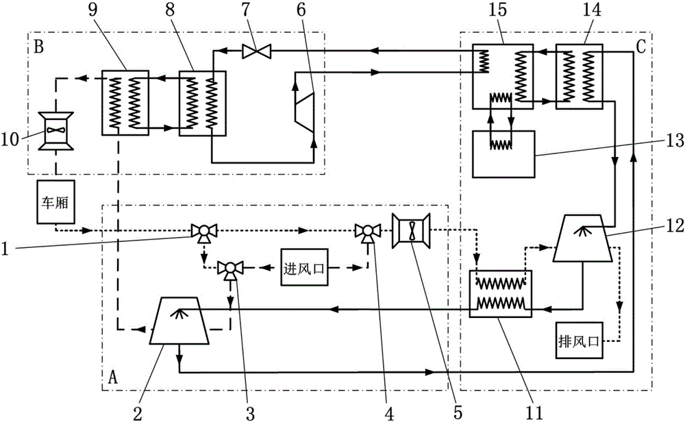
[0029] like figure 1 As shown, a new energy electric vehicle waste heat energy storage air-conditioning system based on solution dehumidification includes a primary return air solution dehumidification system A, an air-conditioning refrigerant circulation system B, and a waste heat energy storage solution regeneration system C.

[0030] The primary return air solution dehumidification system A dehumidifies the mixed incoming air composed of fresh air and return air inside the car, and the air-conditioning refrigerant circulation system B controls the temperature of the mixed incoming air after dehumidification, and sends dry and constant temperature air into the car compartment. High-quality air, the waste heat energy storage solution ...


PUM


Abstract

The invention discloses a new energy electric vehicle waste heat energy storage type air-conditioning system based on solution dehumidification and a method thereof. The air-conditioning system comprises a primary return air solution dehumidification system, an air-conditioning refrigerant circulation system and a waste heat energy storage solution regeneration system. Heat dissipated by batteries of an electric vehicle is absorbed by a phase-change material, and thus the heat dissipation effect of the batteries can be improved, and the temperature of the battery pack can be effectively controlled. By means of the phase-change energy storage technology, heat of condensation and the heat dissipated by the batteries can be efficiently recycled and controllably output, waste heat utilization is achieved, and the overall energy consumption of the electric vehicle is reduced. Through the solution dehumidification technology, separation between a dehumidification link and a temperature control link is achieved, dehumidification is conducted without the need for decreasing the temperature of air to the dew point temperature or below, and the temperature control load of the air-conditioning system is greatly reduced. Through a primary return air mode, fresh air and return air are mixed, so that air quality is guaranteed, and the temperature control load of the air-conditioning system is reduced. Meanwhile, a dehumidification solution can be regenerated repeatedly, and the service life is long.

Description

technical field [0001] The invention relates to the technical field of electric vehicles, in particular to a solution dehumidification-based waste heat energy storage air conditioning system for new energy electric vehicles and a method thereof. Background technique [0002] With the world facing the severe situation of energy shortage and environmental pollution, the energy and environment pressure brought by the traditional automobile industry is increasing. At present, the country is vigorously promoting the development of new energy vehicles, which will help improve my country's current energy consumption structure. Due to the rise and improvement of new power supply technologies such as lithium batteries, sodium-sulfur batteries, nickel-cadmium batteries, and fuel cells, electric vehicles have broad market prospects. [0003] Due to the complex chemical reactions inside the electric vehicle power battery, a large amount of heat will be released during charging and disc...

Claims


Application Information

Patent Timeline
Patent Type & Authority Applications(China)
IPC IPC(8): B60H1/00B60H3/02B60H1/32
CPCB60H1/00385B60H1/00392B60H1/3204B60H3/024B60H2001/00607
Inventor 范利武冯飙朱子钦曾轶许粲羚刘闵婕金虹庆俞自涛胡亚才
Owner ZHEJIANG UNIV
Learn More