
A high-efficiency ball mill with reinforcing ribs

A rib and ball mill technology, applied in the field of ceramic machinery, can solve the problems of increased grinding time, small interlayer space, inconvenient installation and replacement of liners, etc., and achieve the effect of increasing grinding efficiency and shortening grinding time

Active Publication Date: 2018-09-18
佛山市铖罡机械制造有限公司
View PDF4 Cites 0 Cited by
  • Summary
  • Abstract
  • Description
  • Claims
  • Application Information

AI Technical Summary

Problems solved by technology

[0003] When the existing ball mill is used, the grinding material is first poured into the drum body, and then ground, because there are many ores with different textures and sizes in the grinding material, so the length of each grinding time is determined according to the most difficult ore to grind Yes, and in many cases, the grinding material taken out after grinding for a long time still has enough impurities. If the grinding time is estimated based on these impurities that cannot be ground, it will greatly increase the grinding time and delay the progress of the process. The above reasons make It is very difficult to determine the grinding time of the ball mill and to ensure the quality of the ground material. Therefore, the fineness of the ball mill can only be guaranteed through long-term ball milling. How to improve the efficiency of the ball mill and reduce the energy consumption of the ball mill is a main direction for the improvement of the ball mill.
For this reason, people have developed a high-efficiency ball mill with a double-layer cylinder structure, but the interlayer space in the cylinder is small, so there are many problems in installing the liner on the inner wall of the cylinder. If the liner is fixed on the inner wall of the cylinder by screws, Because there is not enough space, it is very inconvenient to install and replace the liner. If the liner is fixed on the inner wall of the cylinder by pasting, the stability of the structure after the liner is installed cannot be guaranteed.

Method used


Image

  • A high-efficiency ball mill with reinforcing ribs
  • A high-efficiency ball mill with reinforcing ribs
  • A high-efficiency ball mill with reinforcing ribs

Examples


Embodiment Construction

[0023] The technical solutions of the present invention will be further described below in conjunction with the accompanying drawings and through specific implementation methods.

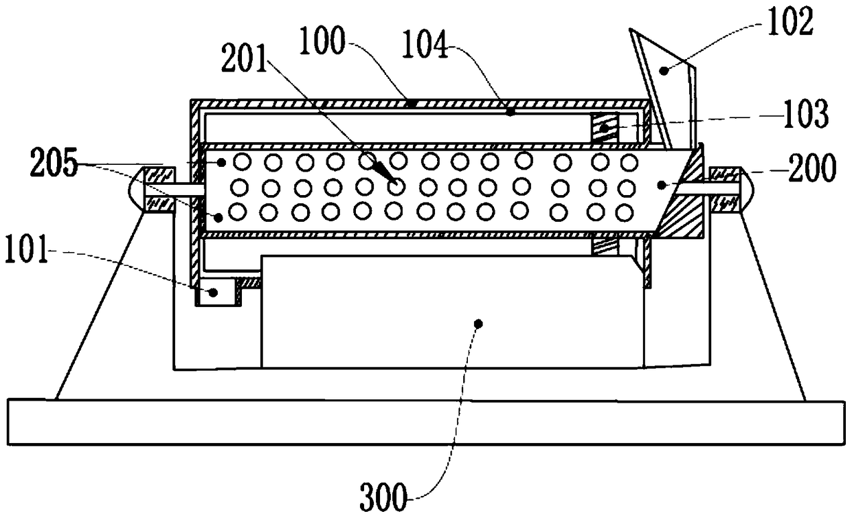
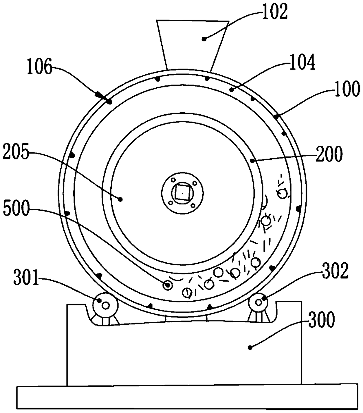
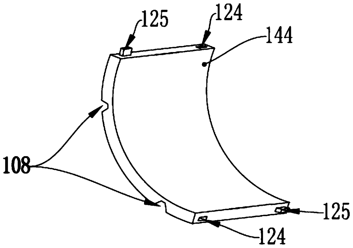
[0024] like Figure 1-3 As shown, a high-efficiency ball mill with reinforcing ribs includes a cylinder body 100 provided with a feed inlet 102 and a discharge outlet 101 and a drive device 300, and the drive device 300 drives the cylinder body 100 to rotate, and the cylinder body 100 is divided into two layers of tubular structure, the first layer is the cylinder shell, the second layer is the primary sieve grinding network pipe 200 with sieve holes, which is made of non-magnetic copper alloy material, the cylinder 100 has a two-layer structure, Grinding balls are placed in the two-layer structure of the cylinder body 100, the grinding balls are magnetic steel balls 500, the feeding port 102 is connected with the cavity of the primary screening grinding network pipe 200, and the discharging port I...


PUM


Abstract

The invention relates to the field of ceramic machinery, in particular to an efficient ball grinding mill with reinforcing ribs. A cylinder body is of a two-layer tubular structure, the first layer is a cylinder body shell, the second layer is a preliminary screening and grinding mesh tube with screening holes, grinding balls are placed inside the cylinder body, a feed port of the cylinder body is connected to a cavity of the preliminary screening and grinding mesh tube, and a discharge port of the cylinder body is connected to a cavity between the inner surface of the cylinder body shell and the outer surface of the preliminary screening and grinding mesh tube; a lining plate is arranged inside the cylinder body shell, is formed by splicing a plurality of lining bricks and is cylindrical, the reinforcing ribs and the lining plate are arranged on the inner surface of the cylinder body shell, grooves are formed in the back surfaces of the lining bricks and cover the reinforcing ribs, the back surface of the lining plate is attached and fixed to the inner surface of the cylinder body shell, and every two adjacent lining bricks are spliced and fixed through mortises and tenons of the lining bricks. The efficient ball grinding mill is convenient to install and stable in structure.

Description

technical field [0001] The invention relates to the field of ceramic machinery, in particular to a high-efficiency ball mill with reinforcing ribs. Background technique [0002] Ball mill is a kind of machine commonly used in the ceramic production process. A common ball mill is mainly composed of a drum with a feeding port and a discharge port and a driving device; the driving device is mainly to drive the rotation of the drum. The drum is equipped with a lining plate, the abrasive will be ground during the rotation process. [0003] When the existing ball mill is used, the grinding material is first poured into the drum body, and then ground, because there are many ores with different textures and sizes in the grinding material, so the length of each grinding time is determined according to the most difficult ore to grind Yes, and in many cases, the grinding material taken out after grinding for a long time still has enough impurities. If the grinding time is estimated ba...

Claims


Application Information

Patent Timeline
Patent Type & Authority Patents(China)
IPC IPC(8): B02C17/10B02C17/22
Inventor 黄婉雅
Owner 佛山市铖罡机械制造有限公司
Learn More