Amalgam electrode, method for manufacturing same, and method for electrochemical reduction of carbon dioxide using same
An amalgam electrode, carbon dioxide technology, applied in the direction of electrodes, electrode coatings, electrode shapes/types, etc., can solve problems such as inapplicability, and achieve the effect of large surface area
- Summary
- Abstract
- Description
- Claims
- Application Information
AI Technical Summary
Problems solved by technology
Method used
Image
Examples
Embodiment 1
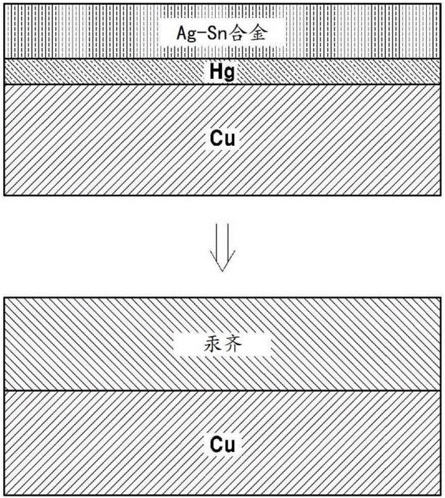
[0052] Example 1: Porous amalgam electrode in which the Ag-Sn layer is formed after the Hg layer is formed
[0053] The mesh-like porous copper electrode was immersed in 10 mMHg(NO 3 ) 2 solution, then pass 8mA / cm 2 constant current reduction to form a Hg layer by electroplating Hg on the surface of the porous copper electrode. An electrode comprising a very thin layer of Hg thereon was placed in a solution containing 0.2 MSC (NH 2 ) 2 and 2MH 2 SO 4 20mMSnSO as electrolyte 4 / 2mMAg 2 SO 4 in solution. Then, apply 10mA / cm to it 2 A constant current followed by electroplating the Ag-Sn layer. In this case, a plate-shaped Sn electrode is used as a counter electrode. After about 1 day, the amalgamation reaction of Hg and Ag-Sn was observed to take place and form a hard solid electrode. Figure 1a A schematic diagram illustrating a method of manufacturing a porous amalgam electrode according to the present embodiment is shown.
Embodiment 2
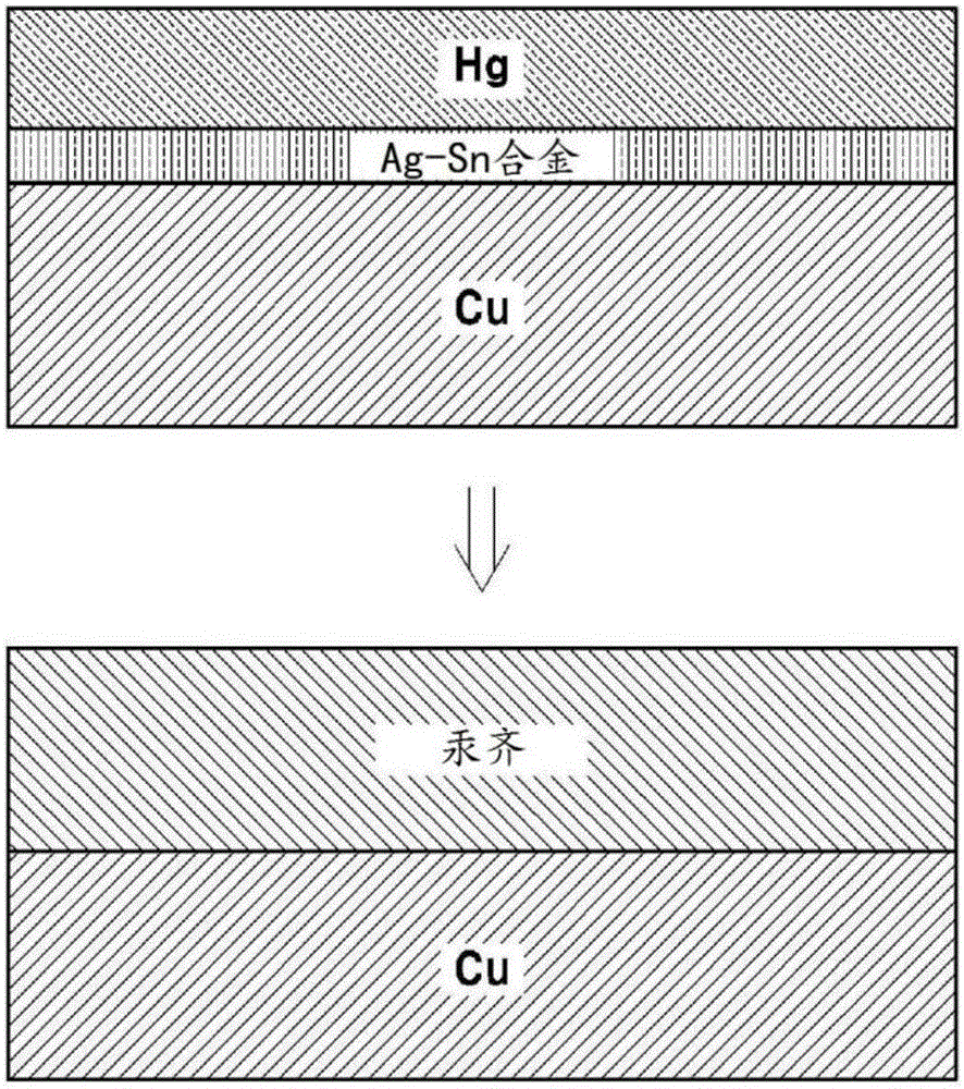
[0054] Example 2: Porous amalgam electrode in which a Hg layer is formed after forming an Ag-Sn layer
[0055] Dip the mesh porous copper electrode into the solution containing 0.2MSC(NH 2 ) 2 and 2MH 2 SO 4 20mMSnSO as electrolyte 4 / 2mMAg 2 SO 4 in solution. Then apply 10mA / cm to it 2 constant current to first form Ag 3 Ag-Sn layer of Sn. In this case, a plate-shaped Sn electrode is used as a counter electrode. The electrode comprising an Ag-Sn layer thereon was placed in 10 mMHg (NO 3 ) 2 solution, and then, through 8mA / cm 2 The constant current reduction followed by electroplating the Hg layer. Over time, an amalgamation reaction of Hg and Ag-Sn was observed to occur and form a porous amalgam electrode. Figure 1b A schematic diagram illustrating a method of producing a porous amalgam electrode according to the present embodiment is shown.
Embodiment 3
[0056] Example 3: Electrochemical reduction of carbon dioxide using a porous amalgam electrode
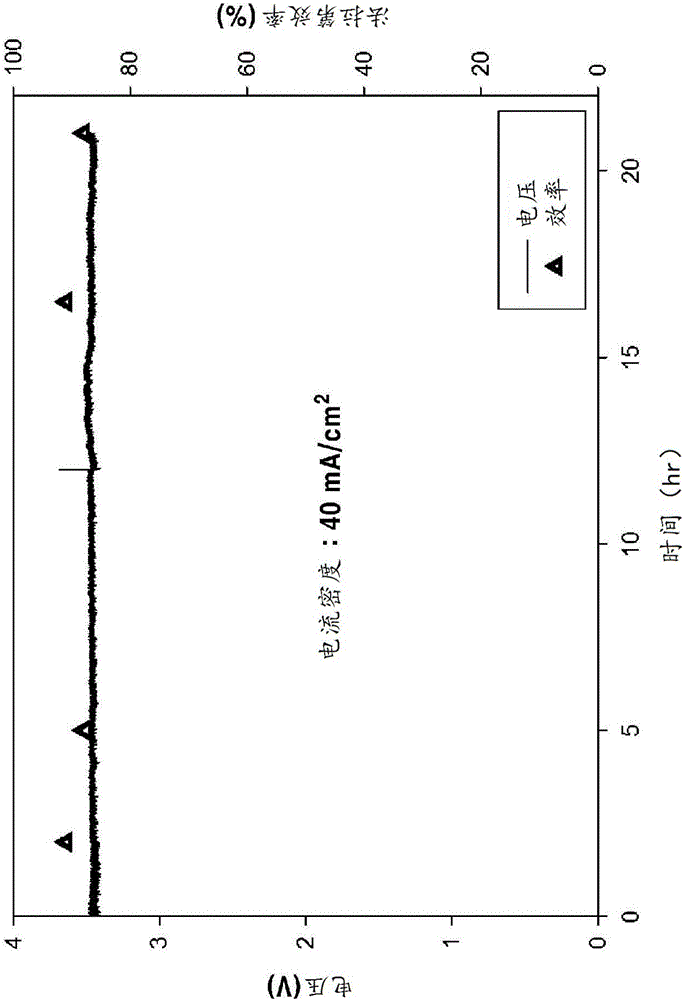
[0057] The porous amalgam electrode prepared in Example 1 was used for the electrochemical reduction of carbon dioxide. Specifically, use 0.5MK 2 SO 4 solution, a porous amalgam electrode, and an IrOx-coated Ti electrode (counter electrode). The constant current circuit KSRnD10A is used to have a 9cm 2 A constant current is applied to the apparent area of the porous amalgam electrode. Then, the efficiency (current efficiency) and duration of formate generation were observed.
[0058] (1) Apply 40mA / cm 2 The situation of the current
[0059] After applying 40 mA / cm to the porous amalgam electrode according to Example 1 2 In the case of a constant current, it was observed that a voltage of about 3.6 V was applied to both ends and the conversion efficiency to formate was as high as about 90% for about 21 h. The result is in figure 2 shown in . In addition, the concentrati...
PUM
| Property | Measurement | Unit |
|---|---|---|
| thickness | aaaaa | aaaaa |
Abstract
Description
Claims
Application Information
 - R&D
- Intellectual Property
- Life Sciences
- Materials
- Tech Scout
- Unparalleled Data Quality
- Higher Quality Content
- 60% Fewer Hallucinations
Browse by: Latest US Patents, China's latest patents, Technical Efficacy Thesaurus, Application Domain, Technology Topic, Popular Technical Reports.
© 2025 PatSnap. All rights reserved.Legal|Privacy policy|Modern Slavery Act Transparency Statement|Sitemap|About US| Contact US: help@patsnap.com


