Grinding roller

A technology of grinding rollers and roller shafts, applied in the field of grinding rollers, can solve problems such as high wear and tear, and achieve the effect of improving cost and saving more costs

Inactive Publication Date: 2016-07-13
LOESCHE GMBH
View PDF9 Cites 1 Cited by
  • Summary
  • Abstract
  • Description
  • Claims
  • Application Information

AI Technical Summary

Problems solved by technology

During operation, the hitherto used bearing arrangements with internal locating bearings and externally located non-locating bearings create more and more common problems and a high degree of wear

Method used


Image

  • Grinding roller
  • Grinding roller

Examples


Embodiment Construction

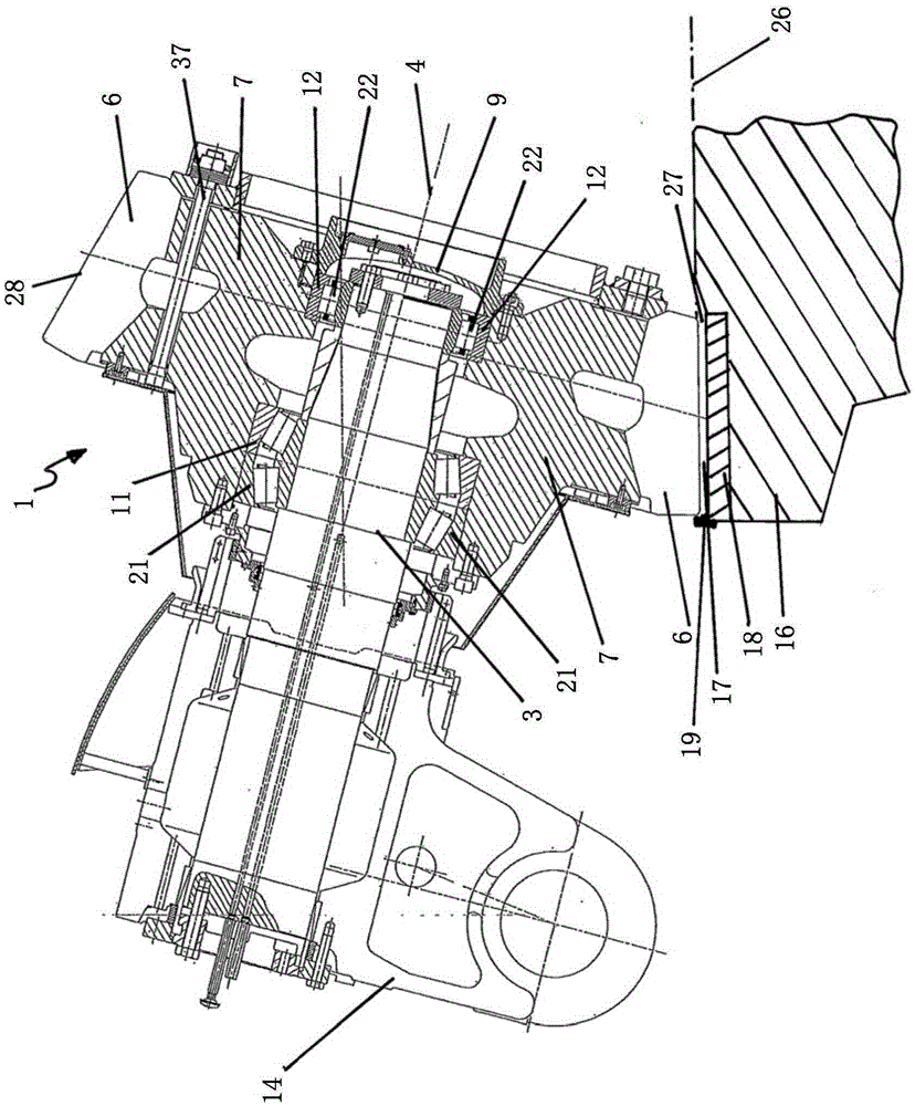
[0040] figure 1 A grinding roll 1 according to the invention is shown in axial section with a roll shaft 3 and a deflection by means of a rocker arm 14 . Considering the function of grinding and comminution of raw materials, the grinding table 16 with the grinding track plate 18, the rib 19 and the surface between the outer peripheral area of ​​the roller sleeve 6 and the surface of the grinding track plate 18 are shown in fragments in the lower area. A part of the corresponding grinding gap 27 between them.

[0041] The outer peripheral region of the roller shell 6 and its slope 28 relative to the grinding roller axis 4 are designed such that the grinding gap 27 runs approximately parallel to the grinding table 26 .

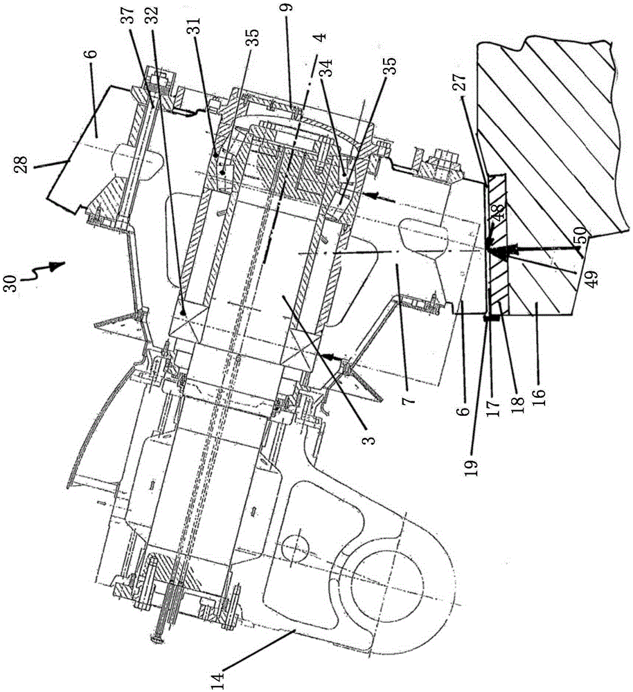
[0042] It should be understood that in figure 1 and figure 2 In , the same reference numerals are used for the same or same type of components on the corresponding grinding roll.

[0043] The roller shaft 3 is rigidly and rotatably fixed firmly in the oute...


PUM


Abstract

The invention relates to a grinding roller having an inclined, fixed inner roller axle (3), a roller jacket (6) being provided on a roller base body (7) . The rotatable roller base body (7) is mounted relatively to the fixed inner roller axle (3) by means of an arranged fixed bearing (11) and a floating bearing (12) which is spaced apart therefrom. The floating bearing (12) is provided in the region of the end face of the roller axle (3) and for supporting the roller base body (7) having the roller jacket (6) so as to allow their rotation, and the fixed bearing (11) is arranged on the roller axle (3) in an outwardly offset manner in the direction of the swing lever (14).

Description

technical field [0001] The invention relates to a grinding roll with an inclined, fixed inner roll shaft, wherein the roll sleeve is arranged on the roll base body, and double row roller bearings are arranged for mounting the roll base body rotatable relative to the fixed inner roll shaft A locating bearing, and a cylindrical roller bearing spaced apart from the double row roller bearing is used as a floating bearing. Background technique [0002] This type of grinding roll is mainly used in air-swept vertical mills for grinding cement raw materials, cement, slag, ore or coal. Examples of such grinding rollers are known from DE 3100341 A1, WO 2005 / 028112 A1 or US 2005 / 0023390 A1. [0003] To be precise, in US 2005 / 0023390 A1 there is also shown a bearing arrangement of a grinding roll with its base body or roll core, and the roll sleeve around its periphery. [0004] exist figure 2 The bearing arrangement of the corresponding grinding rolls so far is shown in a simplified...

Claims


Application Information

Patent Timeline
Patent Type & Authority Applications(China)
IPC IPC(8): B02C15/04
CPCB02C15/04B02C2015/008B02C15/005B02C15/004
Inventor 乔里·贝特沃斯托马斯·莱斯驰迈克尔·克思奈
Owner LOESCHE GMBH
Why Eureka
Try Eureka