
Stereoscopic vision imaging device and stereoscopic vision stimulation equipment

A technology of stereo vision and imaging devices, applied in stereo systems, image communications, electrical components, etc., can solve problems such as defect calibration of imaging systems, limit test accuracy and diversity, bias, etc., and achieve the effect of improving accuracy

Inactive Publication Date: 2016-07-13
BEIJING INSTITUTE OF TECHNOLOGYGY
View PDF7 Cites 8 Cited by
  • Summary
  • Abstract
  • Description
  • Claims
  • Application Information

AI Technical Summary

Problems solved by technology

[0004] Existing devices that provide visual signals generally have large errors due to defects in their imaging systems and calibration biases
Moreover, the provided visual stimulation signals are all planar, which is quite different from the real visual stimulation received by the human eye, which greatly limits the accuracy and diversity of the test.

Method used


Image

  • Stereoscopic vision imaging device and stereoscopic vision stimulation equipment
  • Stereoscopic vision imaging device and stereoscopic vision stimulation equipment
  • Stereoscopic vision imaging device and stereoscopic vision stimulation equipment

Examples


Embodiment Construction

[0031] Exemplary embodiments of the present disclosure will be described in more detail below with reference to the accompanying drawings. Although exemplary embodiments of the present disclosure are shown in the drawings, it should be understood that the present disclosure may be embodied in various forms and should not be limited by the embodiments set forth herein. Rather, these embodiments are provided for more thorough understanding of the present disclosure and to fully convey the scope of the present disclosure to those skilled in the art.

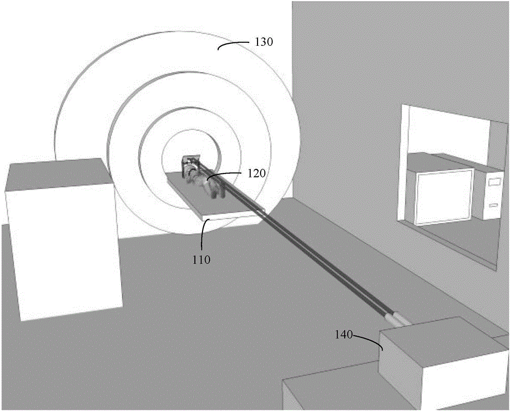
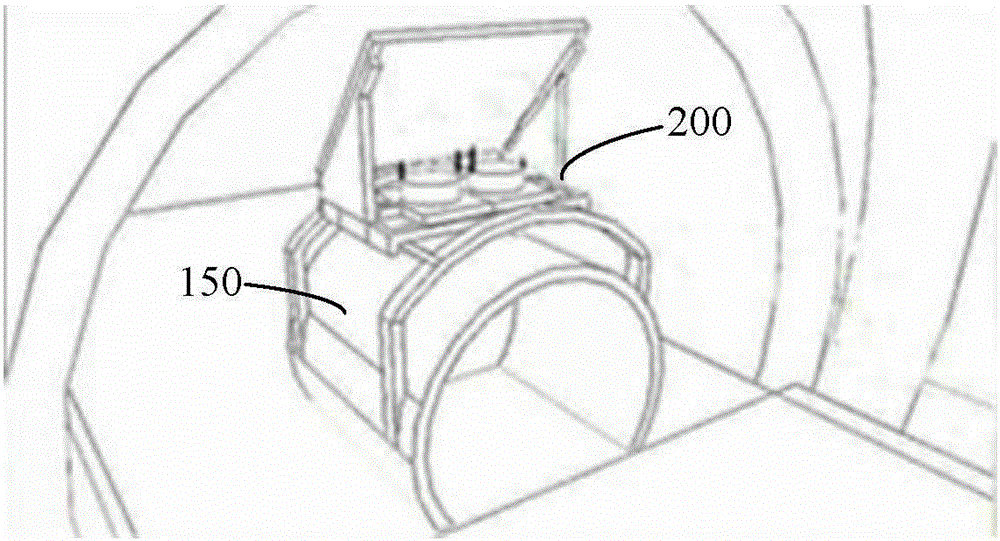
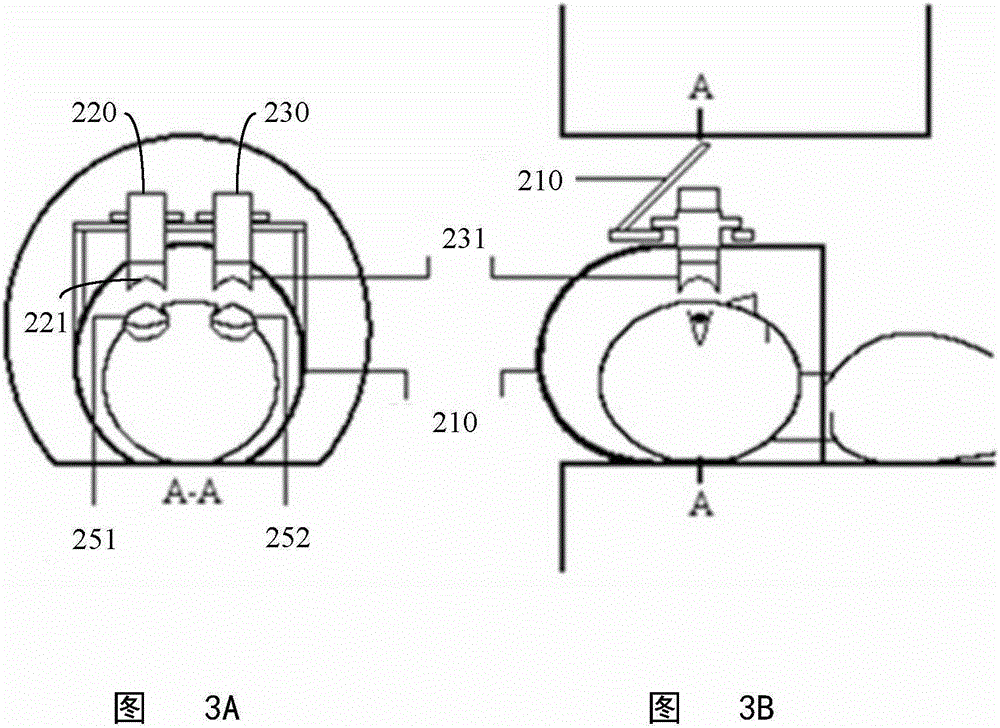
[0032] figure 1 An fMRI system with a stereoscopic visual stimulation device according to one embodiment of the invention is shown. The fMRI system 100 generally includes a scanning couch 110 . The subject 120 lies flat on the scanning bed 110 , and the head of the subject 120 is located in the magnetic resonance scanning device 130 . The magnetic resonance scanning device 130 utilizes the high magnetic field generated by the mag...


PUM


Abstract

The invention discloses a stereoscopic vision imaging device and stereoscopic vision stimulation equipment. The device comprises a mirror used for converting the transmission direction of the light beams of a left-eye image and the light beams of a right-eye image from a horizontal direction to a vertical direction, a left-eye light path channel extending along the vertical direction and used for receiving and transmitting the light beams of the left-eye image reflected by the mirror and carrying out imaging on the exit surface of the left-eye light path channel, a right-eye light path channel extending along the vertical direction and used for receiving and transmitting the light beams of the right-eye image reflected by the mirror and carrying out imaging on the exit surface of the right-eye light path channel, and a support device on which the left-eye light path channel and the right-eye light path channel are arranged movably along the left-right direction and the vertical direction and the mirror is also arranged. The device helps to provide real stereoscopic vision stimulation close to that accepted by the human eye, and provides a novel visual basic research means for related research and test of the visual cortex area in a high-magnetic-field environment.

Description

technical field [0001] The invention relates to the field of magnetic resonance imaging, in particular to a stereoscopic vision imaging device for stereoscopic vision stimulation equipment and the stereoscopic vision stimulation equipment with the stereoscopic vision imaging device. Background technique [0002] The information decoding of the visual function of the human brain has always been a frontier field and a hot issue in brain science research, especially the study of how the brain areas related to the visual function of the human brain will respond to the images seen, and a series of key results have been achieved. The generation of human vision includes two processes: the reflected light of the object is refracted and imaged on the retina through the optical structures in the eye such as the cornea and lens; and then the photoreceptor cells on the retina provide nerve signals to the relevant visual areas of the brain through the optic nerve. form our vision. [00...

Claims


Application Information

Patent Timeline
Patent Type & Authority Applications(China)
IPC IPC(8): H04N13/02
CPCH04N13/236H04N13/239
Inventor 吴景龙
Owner BEIJING INSTITUTE OF TECHNOLOGYGY
Learn More