Three-phase double-T five-level current transformer and control method therefor

A control method and five-level technology, applied in the direction of converting AC power input to DC power output, electrical components, and output power conversion devices, etc., can solve the problems of large volume, large control complexity, complex structure, etc. High reliability, easy expansion level, and high equivalent switching frequency

Active Publication Date: 2016-07-13
SOUTHEAST UNIV
View PDF3 Cites 5 Cited by
  • Summary
  • Abstract
  • Description
  • Claims
  • Application Information

AI Technical Summary

Problems solved by technology

[0005] Purpose of the invention: In order to solve the problems of complex structure, large volume and high control complexity of traditional multi-level converters, the present invention discloses a three-phase double-T five-level converter and its control method, which simplifies The multi-level converter structure is improved, the number of power switching devices used is reduced, its size and cost are reduced, and the system structure is more optimized

Method used


Image

  • Three-phase double-T five-level current transformer and control method therefor
  • Three-phase double-T five-level current transformer and control method therefor
  • Three-phase double-T five-level current transformer and control method therefor

Examples


Embodiment Construction

[0035] The present invention will be further explained below in conjunction with the accompanying drawings.

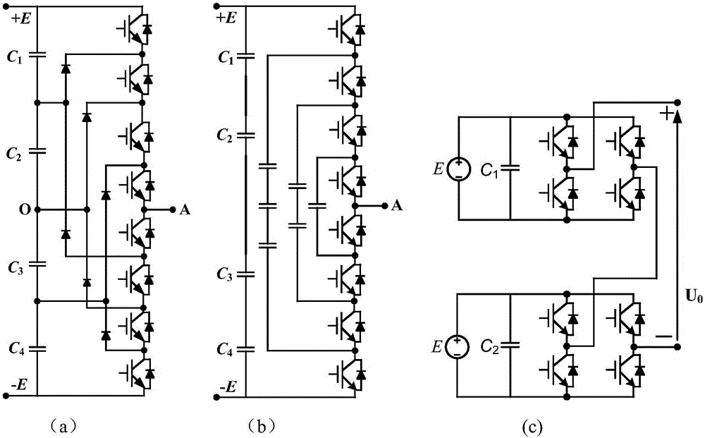
[0036] figure 1 (a), figure 1 (b) and figure 1 (c) shows the topology diagrams of three traditional five-level converters of diode clamp type, flying capacitor clamp type and cascaded H-bridge type respectively.

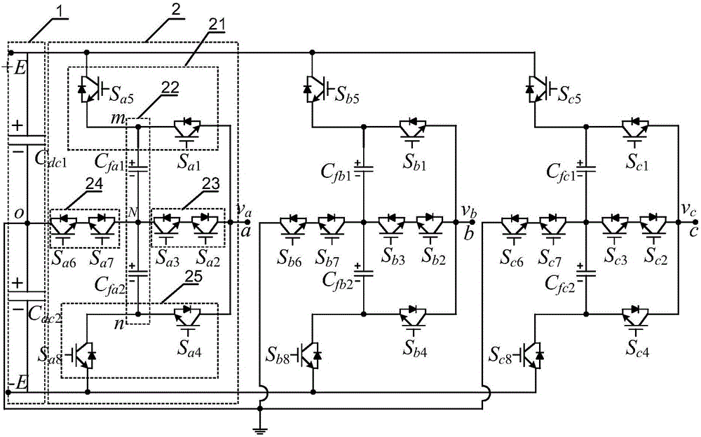
[0037] figure 2Shown is the topology of the three-phase double-T five-level converter proposed by the present invention. The converter is composed of three-phase double-T bridge arms and a DC bus 1 connected in parallel, wherein each phase bridge arm is composed of two three-voltage The flat-T converter topology is combined with two electrolytic capacitors connected in series. The three-phase double T-shaped bridge arms are respectively the A-phase bridge arm, the B-phase bridge arm and the C-phase bridge arm with the same circuit structure; Point clamping bridge arm 24, right middle point clamping bridge arm 23 and lower half bridge bridge arm 25;

[...


PUM


Abstract

The invention discloses a three-phase double-T five-level current transformer and a control method therefor. Each bridge arm of the current transformer is formed by the combination and evolution of two three-level T-shaped current transformer bridge arms and two electrolytic capacitors in series connection. Therefore, the current transformer is small in conduction loss, and is high in efficiency. Compared with a conventional five-level current transformer, the current transformer employs fewer power switching devices, and can generate nine different switching states. Therefore, the current transformer can employ the redundant switching states, and outputs the expected level voltage and controls the balance of the voltage of a flying capacitor at the same time. The current transformer employs a control method based on the multicarrier in-phase laminating SPWM modulation technology, and is enabled to have better quality of output electric energy and higher efficiency. When a fault happens to a power switching tube, the current transformer can carry out fault-tolerant operation through employing the redundant switching states. Therefore, the current transformer is very suitable for an occasion with higher requirements for the reliability and efficiency.

Description

technical field [0001] The invention relates to the field of power electronic multilevel converters, in particular to a three-phase double T-type five-level converter and a control method thereof. Background technique [0002] Since the birth of power electronics technology in the 1950s, after nearly half a century of rapid development, it has been widely used in various fields that require power conversion. The concept of multilevel converter was first proposed by A.Nbaae et al. at the 1980 IAS annual meeting. Among them, the multi-level voltage source converter has become a hot spot for high-voltage and high-power applications due to its good characteristics such as various control methods, low output current harmonic content, and high inverter efficiency. R.H.Baker first proposed the concept of cascaded H-bridge multilevel converter in 1975; Japanese scholars A.Nabae, H.Akagi and others proposed a midpoint clamped multilevel PWM inverter in 1983; T.A.Meynard proposed th...

Claims


Application Information

Patent Timeline
Patent Type & Authority Applications(China)
IPC IPC(8): H02M7/483H02M7/487H02M7/5387
CPCH02M7/483H02M7/487H02M7/53873H02M7/4835H02M1/0095H02M7/4837
Inventor 张建忠徐帅胡省姜永将
Owner SOUTHEAST UNIV
Why Eureka
Try Eureka