
a connector

A technology of connectors and connection positions, which is applied in the direction of connections, components of connection devices, coupling devices, etc., can solve the problems of limited deformation resistance of conductive reeds, and achieve the effect of ensuring deformation resistance

Active Publication Date: 2019-06-07
中航光电(广东)有限公司
View PDF6 Cites 1 Cited by
  • Summary
  • Abstract
  • Description
  • Claims
  • Application Information

AI Technical Summary

Problems solved by technology

[0003] The purpose of the present invention is to provide a connector to solve the problem in the prior art that the connection position between the fixed root of the conductive reed and the elastic overhang end is interfered by the auxiliary reed, which leads to the limitation of the deformation resistance of the conductive reed

Method used


Image

  • a connector
  • a connector
  • a connector

Examples


Embodiment Construction

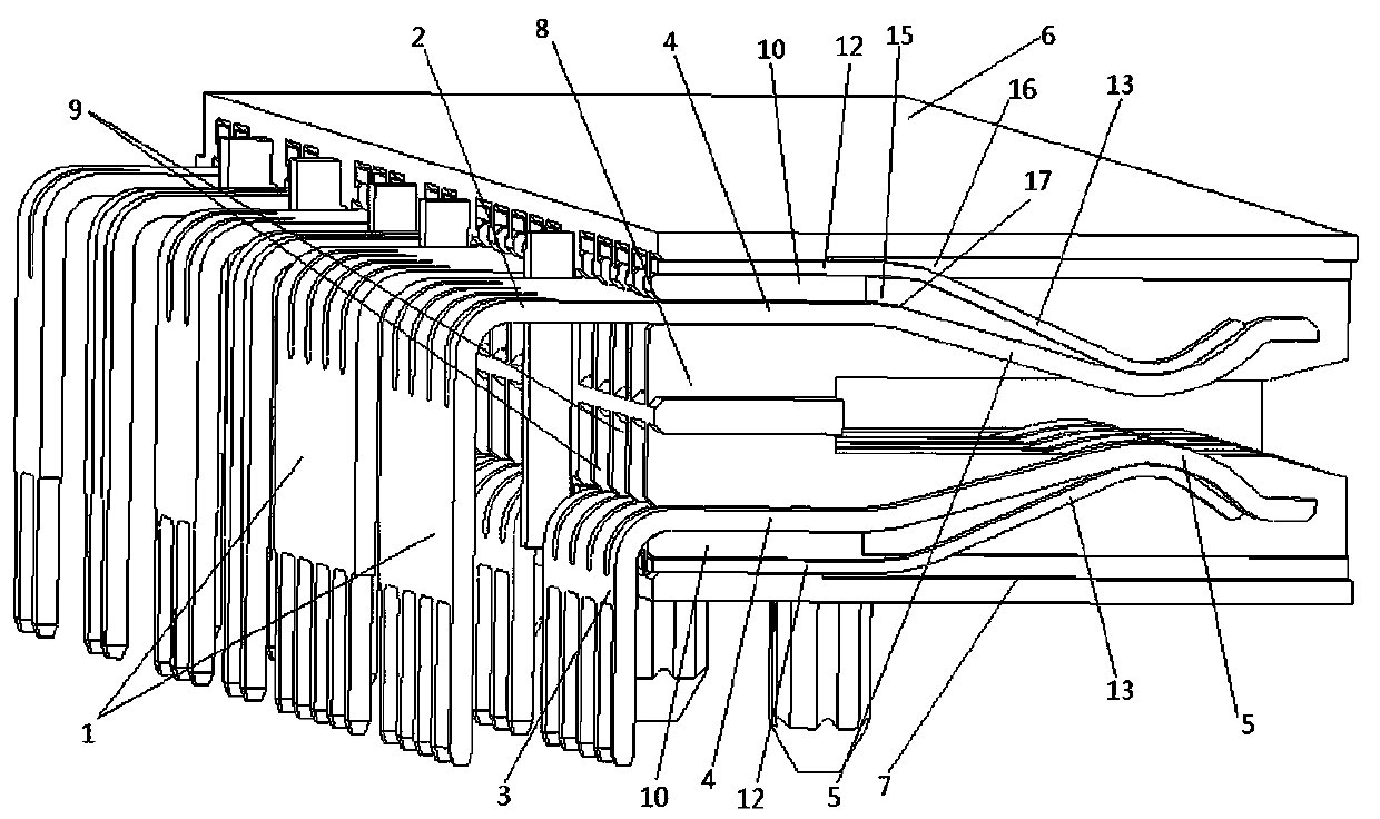
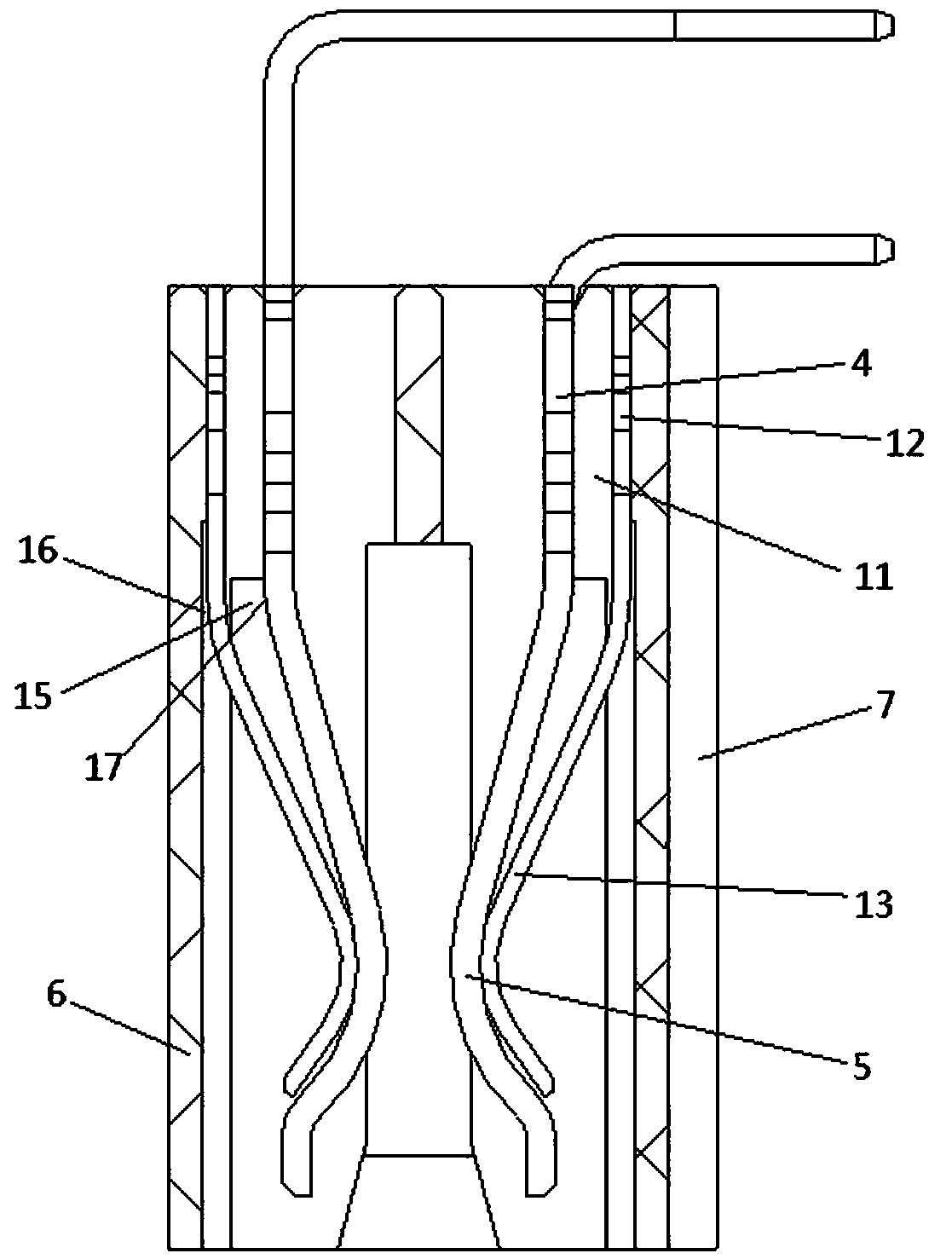
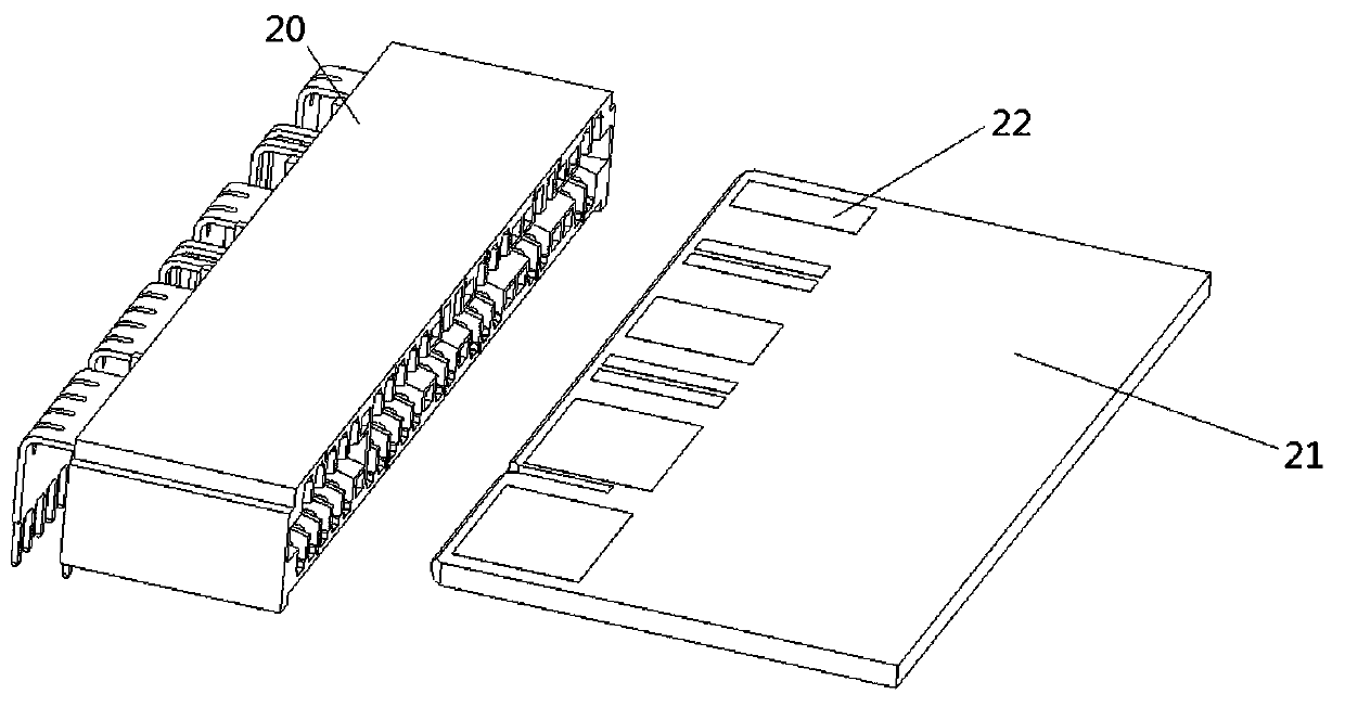
[0014] An implementation example of a connector Figure 1~3 As shown: the connector 20 includes a mounting shell, and multiple pairs of conductive springs 1 and multiple pairs of auxiliary springs corresponding to the conductive springs are arranged in the mounting shell. The conductive springs are made of copper alloy, and the auxiliary springs are made of Made of stainless steel, each pair of conductive reeds includes an upper row of contact pieces 2 and a lower row of contact pieces 3. The upper and lower rows of contact pieces both have a conductive reed fixed root 4 and a forward elastic overhang for printing and printing The golden fingers 22 on the plate 21 are matched with the elastic overhanging ends 5 of the conductive reeds connected, and the conductive reed fixing roots 4 of the upper and lower rows of contacts are a plate-like structure with the thickness of the upper and lower rows of contacts extending in the up and down direction. The elastic overhanging end 5 o...


PUM


Abstract

The invention relates to a connector. The connector includes an installing shell, a conductive spring leaf and an auxiliary spring leaf are arranged on the installing shell, the conductive spring leaf has a conductive spring leaf fixed root and a conductive spring leaf elastic overhanging end elastically overhanging forwards, the auxiliary spring leaf has an auxiliary spring leaf fixed root and an auxiliary spring leaf elastic overhanging end elastically overhanging forwards and used for being matched with the conductive spring leaf elastic overhanging end in a pressing manner, and a conductive spring leaf deformation anti-interference space is arranged between a connecting position of the conductive spring leaf elastic overhanging end and the conductive spring leaf fixed root and the auxiliary spring leaf. The connector provided by the invention solves the problem in the prior art that since the connecting position of the fixed root and the elastic overhanging end of the conductive spring leaf is subjected to interference of the auxiliary spring leaf, a deformation capability of the conductive spring leaf is limited.

Description

Technical field [0001] The invention relates to a connector for electric signal transmission. Background technique [0002] At present, when the printed board is connected, a connector with chip contacts is used when needed. The connector is like the "high-power golden finger connector" disclosed in Chinese patent CN104821450A. The connector includes a mounting plate, that is, a mounting shell. The mounting plate is provided with conductive reeds for mating connection with the golden fingers on the corresponding printed circuit board. , The conductive reed is a kind of leaf contact, an auxiliary spring is arranged between the conductive spring and the mounting shell, and both the conductive spring and the auxiliary spring include a fixed root and an elastic overhang end that is elastically overhanging forward, The elastic overhanging end of the auxiliary spring piece is press-fitted with the elastic overhanging end of the conductive spring piece. The auxiliary shrapnel is provi...

Claims


Application Information

Patent Timeline
Patent Type & Authority Patents(China)
IPC IPC(8): H01R13/115H01R13/187H01R12/71
CPCH01R12/71H01R13/115H01R13/187
Inventor 江后妹薛杨扬吴志富
Owner 中航光电(广东)有限公司
Learn More