Double-color wheel synchronization control method and system for light source, and laser projection equipment

A synchronous control, dual-color wheel technology, applied in optics, instruments, projection devices, etc., can solve the problems of high assembly process difficulty and reduction of monochromatic brightness.

Active Publication Date: 2016-07-13
HISENSE
View PDF5 Cites 8 Cited by
  • Summary
  • Abstract
  • Description
  • Claims
  • Application Information

AI Technical Summary

Problems solved by technology

[0006] In the above-mentioned design method, it is necessary to accurately correspond to the boundary line of the same color partition in the phosphor wheel and the color filter wheel, that is, the projections along the axial direction of the color partition boundary line on the two wheels should be coincident, and this structure The assembly process is difficult. Once the processing is completed, the two wheels are fixed to the shaft, so the offset error caused by processing and installation will not be changed, and there are different degrees of drift in each color wheel, which will cause the two colors in the two-color wheel. There is a certain angle overlap between different colors to form a mixed color, and in order to eliminate the mixed color caused by factors such as assembly error and color wheel drift at the junction of the two colors, it is usually necessary to eliminate the mixed color that overlaps at a certain angle between the two colors color, but this will reduce the brightness of each monochromatic light

Method used


Image

  • Double-color wheel synchronization control method and system for light source, and laser projection equipment
  • Double-color wheel synchronization control method and system for light source, and laser projection equipment
  • Double-color wheel synchronization control method and system for light source, and laser projection equipment

Examples


Embodiment 1

[0059] The embodiment of the present invention provides a method for synchronous control of two-color wheels of a light source, which is applied to the synchronous control of two-color wheels of non-coaxial design, such as Figure 2A shown, including:

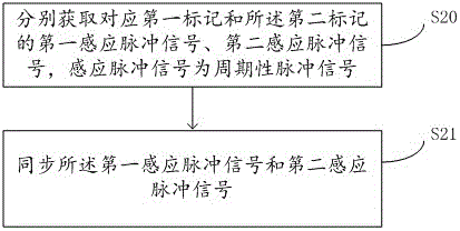
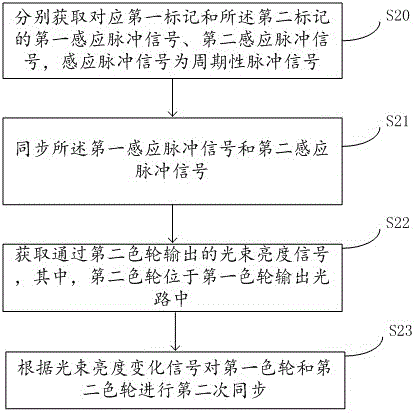
[0060] S20: Obtain a first sensing pulse signal and a second sensing pulse signal corresponding to the first mark and the second mark respectively, where the sensing pulse signal is a periodic pulse signal;

[0061] Wherein, the first mark and the second mark are arranged on the positions corresponding to the first color wheel and the second color wheel respectively, and the first mark and the second mark follow the rotation of the color wheel to obtain the corresponding induction of the first mark and the second mark Pulse signal, the induction pulse signal is a periodic pulse signal, which is synchronized with the rotation period of the color wheel, and the above-mentioned first mark and second mark are the synchronization ma...

Embodiment 2

[0083] Embodiment 2 of the present invention is based on Embodiment 1 and described in detail in conjunction with the accompanying drawings.

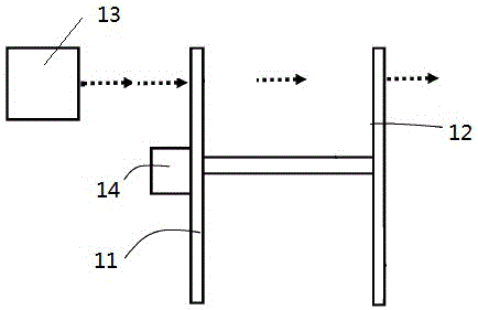
[0084] Specifically, Embodiment 3 of the present invention provides a two-color wheel synchronous control method for a light source, which is applied to a laser light source with a non-coaxial design of the two-color wheel. An example of the position and structure relationship of the non-coaxial two-color wheel can be shown in Figure 2 , the first color wheel 1 and the second color wheel 2 are respectively connected with drive motor shafts 12 and 22 to drive the wheel surface to perform periodic rotation, such as image 3 As shown, the extension lines of the centers of the drive motor shafts 12 and 22 intersect to form an angle, which can be an acute angle, a right angle or an obtuse angle, and in this example is a vertical relationship. That is to say, the rotation axes of the first color wheel 1 and the second color wheel 2 are not co...

Embodiment 3

[0116] The embodiment of the present invention also proposes a two-color wheel synchronous control system for the light source, such as Figure 11 As shown, a first color wheel 21 is included, and the first color wheel 21 includes a first mark (not shown in the figure); a second color wheel 22, and the second color wheel 22 includes a second mark (not shown in the figure), Where the first mark corresponds to the position of the second mark on the corresponding color wheel, the system further includes a first sensor 23 , a second sensor 24 , a third sensor 25 and a synchronous control unit 26 .

[0117] Wherein, the first sensor 23 is used to obtain the first sensing pulse signal of the first mark of the first color wheel, which is an infrared sensor or a light sensor; the second sensor 24 is used to obtain the first sensing pulse signal of the second mark of the second color wheel. The second induction pulse signal is an infrared sensor or a light sensor.

[0118] The synchro...


PUM


Abstract

The invention discloses a double-color wheel synchronization control method for a light source, and the method comprises the steps: setting a first color wheel and a second color wheel in a non-coaxial manner; respectively setting a first mark and a second mark on the first and second color wheels; respectively obtaining a first inductive pulse signal and a second inductive pulse signal, which are respectively corresponding to the first mark and the second mark; carrying out the synchronization of the first and second inductive pulse signals, and achieving a purpose of synchronization of the first and second color wheels in an indirect manner. The invention also provides a double-color wheel control system corresponding to the method, and laser projection equipment employing the above system and method.

Description

[0001] This application claims the priority of the Chinese invention application 201510739594.2 filed on November 4, 2015 with the title of "Double-color wheel synchronous control method, system and laser projection equipment for light source". technical field [0002] The invention relates to the technical field of laser light sources, in particular to a method and system for synchronous control of a two-color wheel of a light source, and a laser projection device. Background technique [0003] As a solid-state light source, laser light source has a series of advantages such as high brightness, high efficiency, long life, good color gamut, and environmental protection, and has become the choice of emerging projection light source. [0004] Among the light sources composed of laser light and fluorescent powder stimulated to produce fluorescence currently used in the industry, blue laser light is usually used as the laser light source and excitation light source of the laser p...

Claims


Application Information

Patent Timeline
Patent Type & Authority Applications(China)
IPC IPC(8): G03B21/20
CPCG03B21/204G03B21/2053G03B21/206
Inventor 崔荣荣林信宏李健锋
Owner HISENSE
Why Eureka
Try Eureka