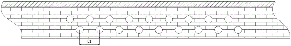
Waste heat recycling system with variable spacing between heat pipes
A technology of waste heat recovery system and heat pipe, which is applied in the field of waste heat recovery system, can solve the problems of low waste heat recovery efficiency and achieve the effects of improving heat exchange efficiency, reducing flow resistance, optimizing heat collection effect and flow resistance
- Summary
- Abstract
- Description
- Claims
- Application Information
AI Technical Summary
Problems solved by technology
Method used
Image

Examples
Embodiment Construction
[0037] The specific embodiments of the present invention will be described in detail below in conjunction with the accompanying drawings.
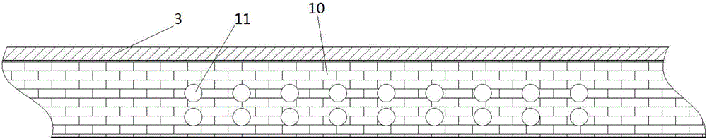
[0038] A heat pipe waste heat recovery system, comprising a heating device (i.e. a device that provides waste heat), a heat pipe 1, the heating device includes a casing, a channel, an insulating material is arranged between the casing and the channel, and the heat pipe 11 includes an evaporation end and a condensation end, the evaporation end of the heat pipe 11 is set in the heat preservation material.
[0039] Compared with common heat exchange tubes, the present invention can greatly improve heat absorption efficiency by arranging heat pipes as waste heat recovery pipes.
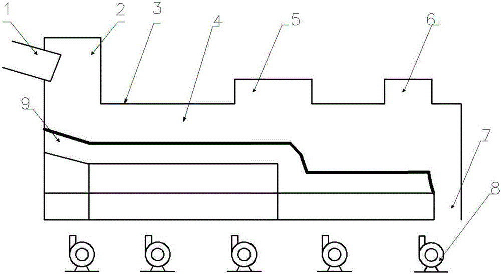
[0040] As preferably, the heating equipment is a grating cooler 4, for example, as figure 1 shown.
[0041] figure 1 A preferred grate cooler 4 for cement production is shown. The grate cooler 4 includes a kiln head cover 2, a grate cooler shell 3, a high-temperatu...
PUM
 Abstract
Description
Claims
Application Information
 - R&D
- Intellectual Property
- Life Sciences
- Materials
- Tech Scout
- Unparalleled Data Quality
- Higher Quality Content
- 60% Fewer Hallucinations
Browse by: Latest US Patents, China's latest patents, Technical Efficacy Thesaurus, Application Domain, Technology Topic, Popular Technical Reports.
© 2025 PatSnap. All rights reserved.Legal|Privacy policy|Modern Slavery Act Transparency Statement|Sitemap|About US| Contact US: help@patsnap.com