Intermediate-speed large-torque radial plunger hydraulic motor

A technology of hydraulic motor and high torque, applied in the field of medium-speed and high-torque radial piston hydraulic motors, can solve the problems of poor processability, fluctuation of output torque of crankshaft 3, poor positioning ability of connecting rod 6, etc. Efficiency and reliability, reduced friction and heat generation, good effect on neutrality and stability

Active Publication Date: 2016-07-13
INTRA ITAL HYDRAULICS FOSHAN SHUNDE
View PDF9 Cites 4 Cited by
  • Summary
  • Abstract
  • Description
  • Claims
  • Application Information

AI Technical Summary

Problems solved by technology

[0006] 1. The outer surface 501 of the bearing seat 5 is a cylindrical surface, and the inner concave surface 603 of the connecting rod 6 that cooperates with the cylindrical surface 501 of the bearing seat 5 is still a cylindrical surface. The fit between the cylindrical surfaces cannot be constrained along the axis of the cylinder, that is, the axis degrees of freedom in the y direction
Therefore, as the operating speed increases, the positioning ability of the connecting rod 6 is poor and the stability is poor
[0007] 2. The connecting rod 6 and the retaining ring 7 are completely rigid connections of mechanical components. There is a gap between the groove 601 of the connecting rod 6 and the inner hole 701 of the retaining ring. As the speed increases, the centrifugal force increases, and the connecting rod 6 and the retaining ring There is a mechanical impact between 7, resulting in noise
[0009] 4. It can be seen from the motion law of the connecting rod 6 above that the driving force of the connecting rod 6 to the crankshaft 3 fluctuates according to the cosine law, that is, the driving force is equal to Fcosθ, where F is determined by the diameter of the piston 8 and the hydraulic oil pressure. It can be seen that the output torque of the crankshaft 3 fluctuates
[0010] 5. In addition to the defects in the above-mentioned structural principles, the motor with this structural form also has technical deficiencies
[0015] 1. From the above analysis, it can be known that the crankshaft 3 rotates once, and the spring 6 stretches once. The higher the speed, the higher the frequency of spring 6 stretching and stretching, and the easier it is to fatigue and break. Therefore, the spring 6 has become one of the bottlenecks for increasing the motor speed.
[0016] 2. With the expansion and contraction of the spring 6, the contact stress between the oil cylinder 4 and the crankshaft 3, and between the piston 5 and the cylinder head 7 changes periodically. According to the knowledge of contact mechanics, the alternating contact stress is easier to make than the static contact stress. Fatigue failure on the contact surface
[0019] The application publication number published on February 4, 2015 is CN104329217A, which discloses a telescopic swing cylinder hydraulic motor and its eccentric shaft spherical surface processing method. The invention uses technological means to process small liquid storage holes on the crankshaft spherical surface to improve Although its self-lubricating performance can reduce friction to a certain extent and increase speed, the physical fact of sliding friction between the oil cylinder and the spherical surface of the crankshaft has not changed, and is still restricted by the PV value of the friction pair.
[0020] The application publication number published on April 3, 2013 is CN103014587A, which discloses a method of thermally spraying molybdenum coating on the surface of the crankshaft. This invention sprays a layer of metal coating on the spherical surface of the crankshaft to increase its self-lubricating properties. Wear resistance, this method has achieved good results on large displacement (3600ml / r and above) hydraulic motors, but the same as the invention method disclosed in the above-mentioned CN104329217A, the physical fact of sliding friction between the oil cylinder and the spherical surface of the crankshaft has not changed, still Restricted by the PV value of the friction pair, it is still not suitable for medium-speed working conditions
[0023] 2. Same as the previous solution, the physical fact of the sliding friction between the oil cylinder 4 and the spherical surface of the crankshaft 2 has not changed, and it is still restricted by the PV value of the friction pair, and it is still not suitable for medium-speed working conditions
[0027] 2. The trunnion is a cantilever beam structure, there is bending stress, and the mechanical characteristics are not good
[0029] 4. There is a damping hole inside the piston. The piston is not a completely hollow thin-walled structure and has a large weight. Its disadvantages are as mentioned above.
[0030] 5. Two cantilever trunnions are set on the cylindrical swing cylinder. The coaxiality, smoothness and surface hardness of the two trunnions have high requirements, so the processing technology is not good
but as above Figure 7 In the structure shown, the inherent shortcomings of the trunnion structure have not changed, and the oil distribution mechanism does not have the ability to automatically compensate

Method used


Image

  • Intermediate-speed large-torque radial plunger hydraulic motor
  • Intermediate-speed large-torque radial plunger hydraulic motor
  • Intermediate-speed large-torque radial plunger hydraulic motor

Examples


Embodiment Construction

[0113] In order to make the technical features, objectives and beneficial effects of the present invention clearer, the specific implementation manners of the present invention will be described in detail below in conjunction with the accompanying drawings.

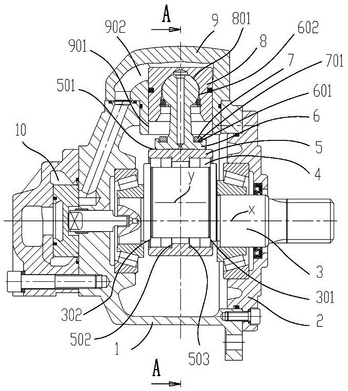
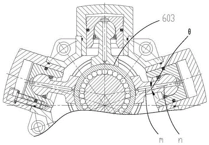
[0114] Such as Figure 8 As shown, a medium-speed high-torque radial plunger hydraulic motor includes a housing 1, a crankshaft 2 for outputting rotational speed and torque to the outside, a bearing 29 arranged in the inner hole of the housing 1 and the front cover 27, and the outer casing is eccentrically mounted on the crankshaft 2. The roller 3 of the shaft section 201, the roller 3 is sleeved in the inner hole 401 of the bearing sleeve 4, radially star-shaped and uniformly fastened to the cylinder head 5 of the housing 1, distributed radially along the bearing seat 4 and the upper and lower ends The telescopic sleeve 6 that is respectively offset against the outer spherical surface 501 of the cylinder head 5 and the o...


PUM


Abstract

The invention relates to an intermediate-speed large-torque radial plunger hydraulic motor which comprises a casing (1), a crankshaft (2), a roller (3), a bearing bush (4), a cylinder head (5), a telescopic sleeve (6), a retainer ring (7), a hanger rod (8) and a drive shaft (10).The telescopic sleeve (6) is arranged along the radial direction of the bearing bush (4), and the upper end and the lower end of the telescopic sleeve (6) are respectively abutted against an external spherical surface (501) of the cylinder head (5) and an external spherical surface (402) of the bearing bush (4).The lower end of the telescopic sleeve (6) is closely attached to the external spherical surface (402) of the bearing bush (4) by the retainer ring (7).The upper end of the telescopic sleeve (6) is closely attached to the external spherical surface (501) of the cylinder head (5) by the hanger rod (8).Two ends of the drive shaft (10) are respectively connected with the crankshaft (2) and an oil distributing mechanism (9).The roller (3) is inserted in an inner bore (401) of the bearing bush; and the crankshaft (2) comprises an eccentric section (201).Compared with the prior art, the radial plunger hydraulic motor has the advantages of highly increased revolution speed and compact structure.

Description

technical field [0001] The invention relates to the technical field of hydraulic components, in particular to a medium-speed high-torque radial plunger hydraulic motor. Background technique [0002] The typical structure of the radial plunger hydraulic motor is that the plungers are distributed radially in a star shape along the drive shaft, and the movement plane of the plunger is perpendicular to the drive shaft. Torque applications. [0003] However, the actual use in the market today shows that the common radial piston hydraulic motor uses a rotating speed lower than 300r / min. According to the conventional view in the hydraulic motor industry that 500r / min is used as the boundary, higher than 500r / min is classified as a high-speed motor, and less than 500r / min is classified as a low-speed motor. The radial piston hydraulic motors on the market today are large Some should be classified as low-speed high-torque radial piston hydraulic motors, and high-speed motors higher...

Claims


Application Information

Patent Timeline
Patent Type & Authority Applications(China)
IPC IPC(8): F03C1/22F03C1/38F03C1/28F03C1/32
CPCF03C1/22F03C1/223F03C1/0406F03C1/0415F03C1/0444
Inventor 叶春浓蒋志坚葛正菊
Owner INTRA ITAL HYDRAULICS FOSHAN SHUNDE
Why Eureka
Try Eureka