


Quick Research
Generate reliable direction feasibility study reports for your R&D in just a few steps.

Technical Q&A
Discover and master advanced knowledge NOW. Basics, ideas, possibilities, all at once.

Find Solutions
As an expert in R&D theories, this can generate solutions to your technical problems instantly.

Evaluate Feasibility
Analyze your overall solution with one click, know your potential R&D risks in advance.

Monitor Landscape
Get weekly tech updates, stay abreast of the latest tech innovations and key insights.
An energy supply method and system using carbon dioxide as a carrier
An energy supply system, carbon dioxide technology, applied in chemical instruments and methods, applications, inorganic chemistry, etc., can solve the problems of insufficient development and utilization of carbon dioxide, and achieve the effect of reducing the number of tanks, high efficiency, and good safety
- Summary
- Abstract
- Description
- Claims
- Application Information
AI Technical Summary
Problems solved by technology
Method used
Image


Examples
Embodiment 1
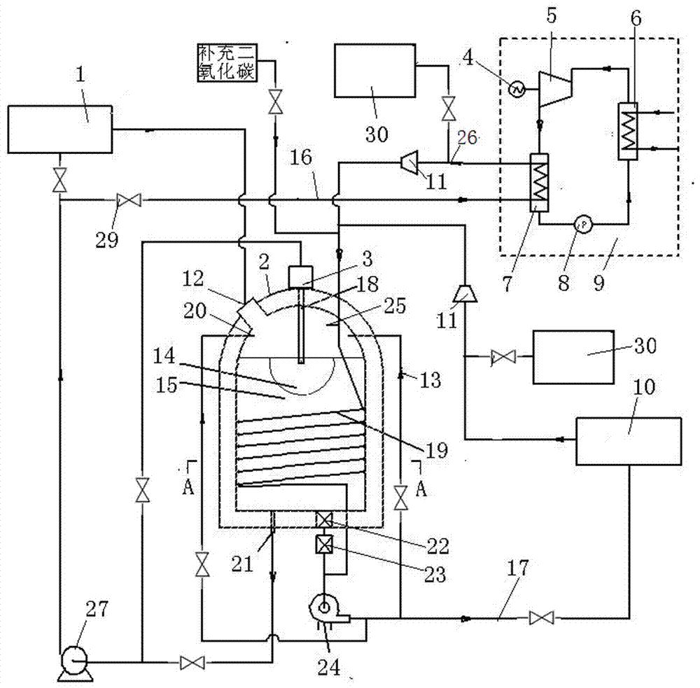
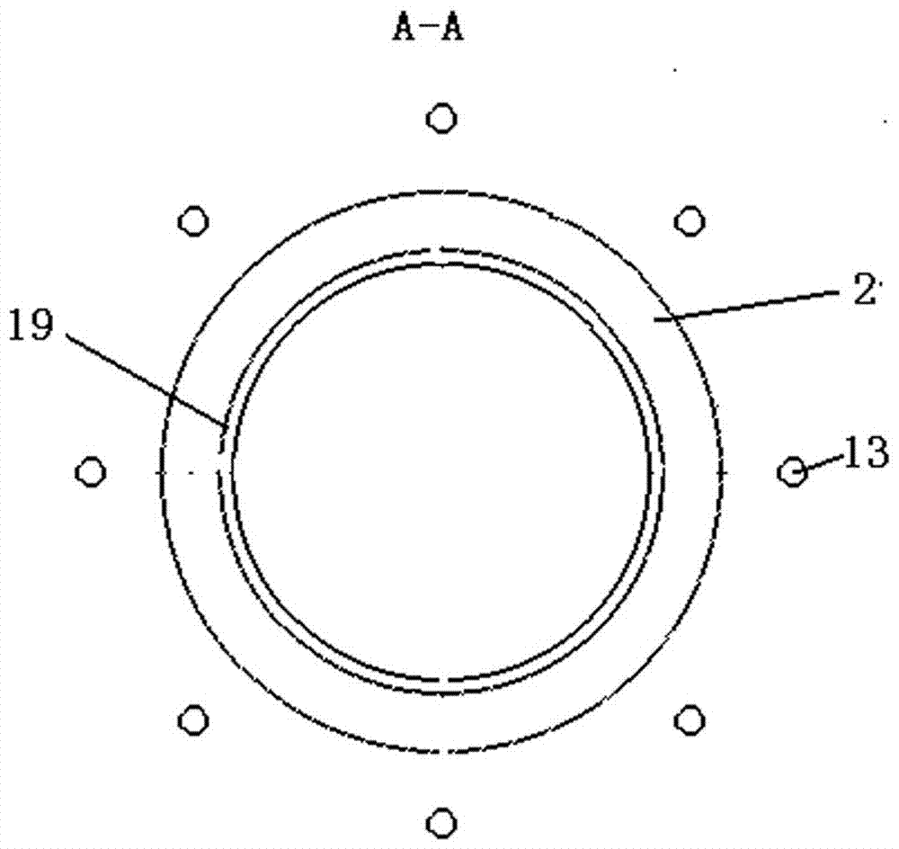
[0024] The present invention uses carbon dioxide as the energy supply system of the carrier, such as Figure 1 ~ Figure 3 As shown, it includes a dry ice manufacturing machine 1, a dry ice storage tank 2, a compressor 11, a dry ice filter 22, a gas-liquid separator 23, a low-temperature fan 24, a liquid carbon dioxide pump 27, a low-temperature liquid carbon dioxide power generation device 9 and a low-temperature carbon dioxide gas user 10 . The low-temperature carbon dioxide gas user is household refrigeration and air-conditioning equipment, and the low-temperature liquid carbon dioxide power generation device 9 is provided with a generator 4 , an expander 5 , an evaporator 6 , a condenser 7 and a circulating pump 8 . The working medium outlet of the expander is connected to the circulation pump through the condenser, and the circulation pump outlet is connected to the working medium inlet of the expander through the evaporator. The working medium is Freon, the heating mediu...
Embodiment 2
[0028] Another embodiment of the present invention is as Figure 4 As shown, it includes a dry ice maker 1 , a dry ice storage tank 2 , a compressor 11 , a dry ice filter 22 , a gas-liquid separator 23 , a liquid carbon dioxide pump 27 , a low-temperature fan 24 and a low-temperature liquid carbon dioxide power generation device 9 . The low-temperature liquid carbon dioxide power generation device 9 is provided with a generator 4 , an expander 5 , an evaporator 6 , a condenser 7 and a circulating pump 8 . The working medium outlet of the expander is connected to the circulation pump through the condenser, and the circulation pump outlet is connected to the working medium inlet of the expander through the evaporator. The working medium is non-freon refrigerant, the heating medium of the evaporator 6 is air, and the air goes through the shell side of the evaporator. The upper outlet of the liquid carbon dioxide and the lower outlet of the liquid carbon dioxide are connected to ...
Embodiment 3
[0031] The third embodiment of the present invention is as Figure 5 As shown, it includes a dry ice maker 1 , a dry ice storage tank 2 , a compressor 11 , a dry ice filter 22 , a gas-liquid separator 23 , a low-temperature fan 24 and a low-temperature carbon dioxide gas power generation device 28 . The low-temperature carbon dioxide gas outlet in the lower part of the dry ice storage tank is connected to the inlet of the low-temperature fan 24 through a dry ice filter and a gas-liquid separator. The gas pipeline 17 is connected to the low-temperature carbon dioxide gas power generation device, and valves 29 are respectively provided in the two pipelines. The outlet of the low-temperature carbon dioxide gas power generation device is connected to the high-temperature carbon dioxide gas inlet through the compressor 11 and the high-temperature carbon dioxide gas pipeline 26 . The high-temperature carbon dioxide gas inlet is divided into two paths, one path leads to the upper sp...
PUM
| Property | Measurement | Unit |
|---|---|---|
| critical temperature | aaaaa | aaaaa |
Abstract
Description
Claims
Application Information
 - R&D Engineer
- R&D Manager
- IP Professional
- Industry Leading Data Capabilities
- Powerful AI technology
- Patent DNA Extraction
Browse by: Latest US Patents, China's latest patents, Technical Efficacy Thesaurus, Application Domain, Technology Topic, Popular Technical Reports.
© 2024 PatSnap. All rights reserved.Legal|Privacy policy|Modern Slavery Act Transparency Statement|Sitemap|About US| Contact US: help@patsnap.com