
A semi-hollow pin plastic forming method

A plastic forming and semi-hollow technology, applied in forging/pressing/hammer devices, forging/pressing/hammering machinery, manufacturing tools, etc., can solve the problems of small range of processing materials, products with burrs, and affecting product quality. Achieve the effect of material saving, simple process and excellent smooth quality

Active Publication Date: 2018-11-09
丽水市知源科技有限公司
View PDF1 Cites 0 Cited by
  • Summary
  • Abstract
  • Description
  • Claims
  • Application Information

AI Technical Summary

Problems solved by technology

But its disadvantages are: the process is more complicated, there is still room for improvement in material utilization, the range of processed materials is small, and the product has burrs, which affect product quality

Method used


Image

  • A semi-hollow pin plastic forming method
  • A semi-hollow pin plastic forming method
  • A semi-hollow pin plastic forming method

Examples


Embodiment Construction

[0034] The present invention will be further described in detail below in conjunction with the accompanying drawings and embodiments.

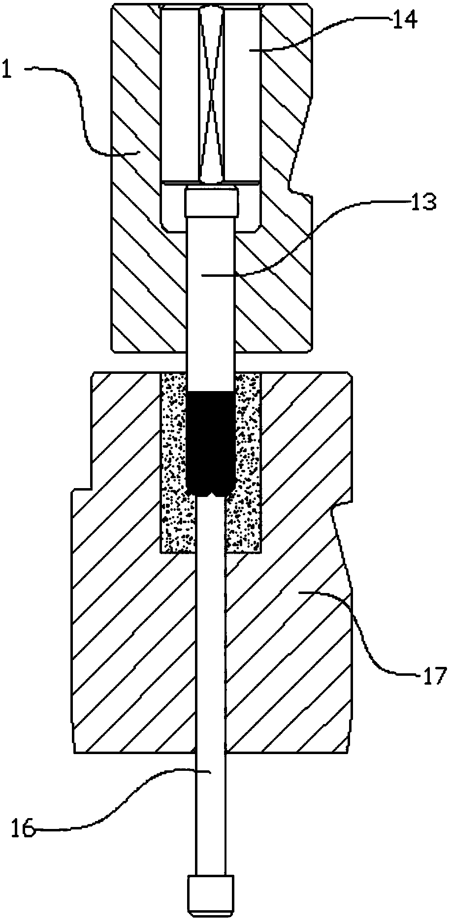
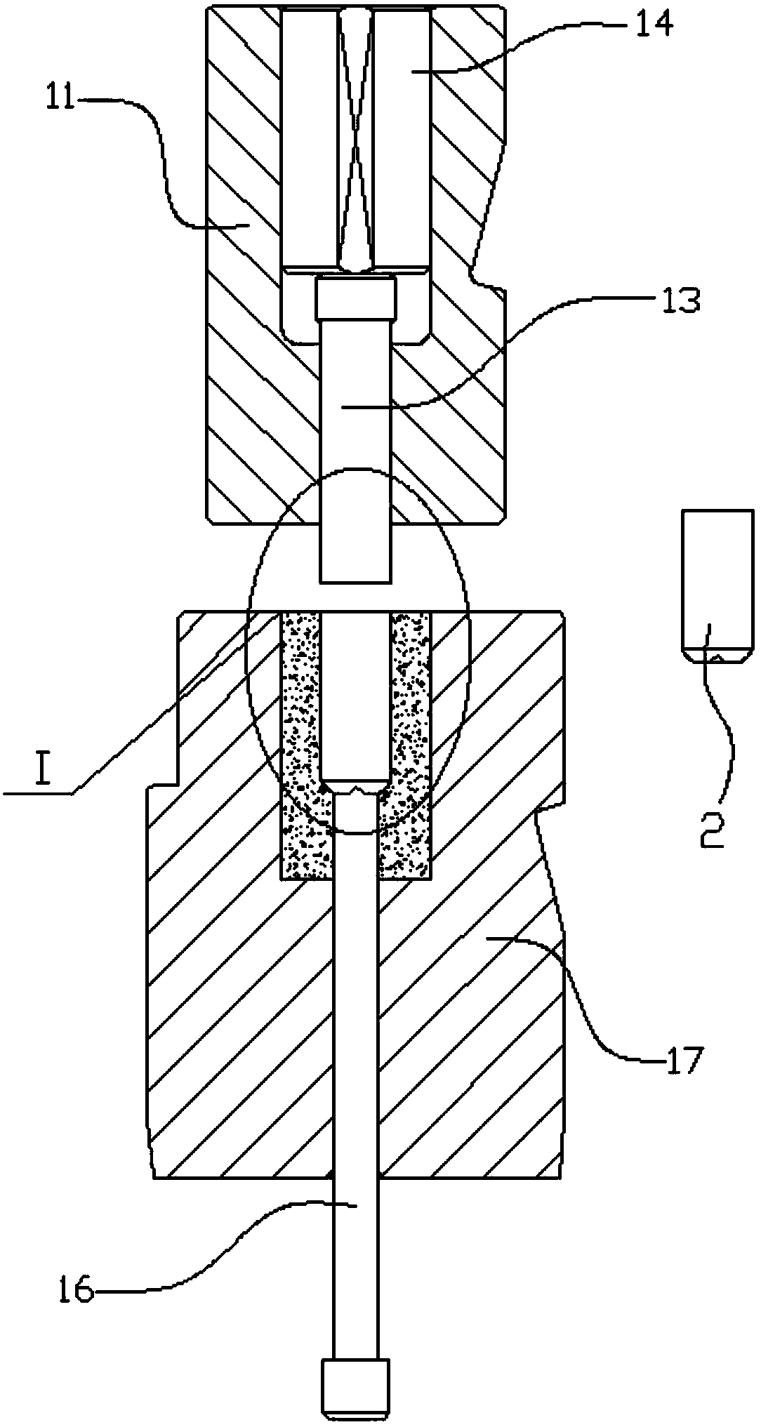
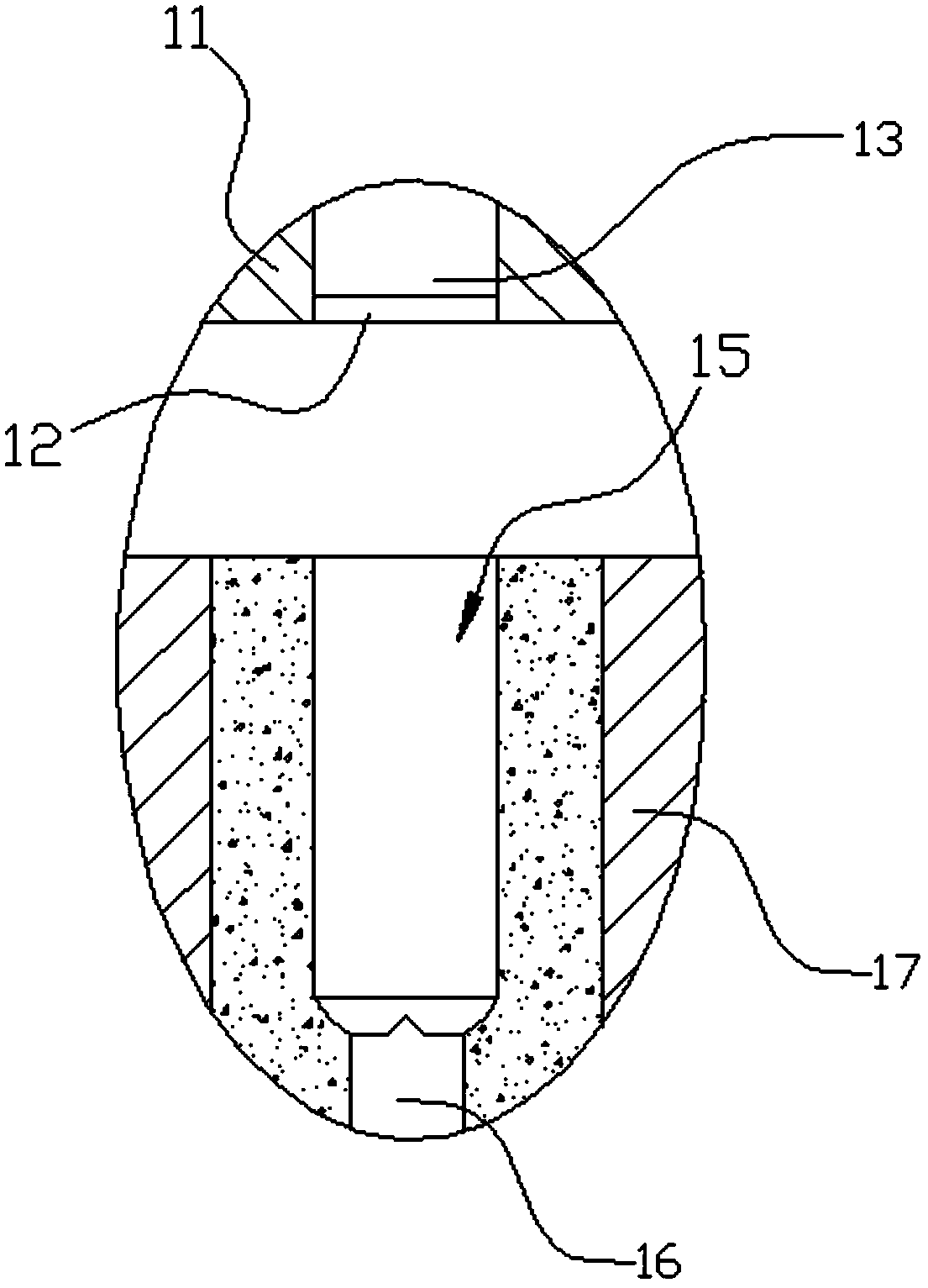
[0035] Such as Figure 1-12 As shown, the plastic forming method of the semi-hollow shaft pin in this embodiment is carried out according to the following steps:

[0036] Step 1: Squeeze the part blank into the bottom mold through the first stamping die 1, so that the bottom of the blank is rounded and shaped to obtain the required dimensions for the tapered hole at the tail and the upsetting of the rod;

[0037] Step 2, extruding the part 2 after step 1 through the second stamping die 3, obtaining the pre-formed hole of the head, reducing the diameter and chamfering, and upsetting the rod and head to reach the required size;

[0038]Step 3: Back-extrude the head of the part 2 after step 2 to extract holes through the third stamping die 4 to obtain the required size of the hollow hole depth of the head, and further upsetting the head and the ...


PUM


Abstract

The invention discloses a plastic forming method of a semi-hollow shaft pin. The plastic forming method comprises the following steps: step 1, extruding a part blank through a first punching die (1) to obtain needed sizes of a tail filleted corner, a bottom surface tapered hole and a rod part; step 2, extruding a part (2) in the step 1 through a second punching die (3), so as to obtain a needed size of a head pre-formed hole, carry out hole shrinkage and chamfering, and upset the rod part and a head to the needed sizes; step 3, extruding the part (2) in the step 2 through a third punching die (4) to obtain the needed size of the depth of a head hollow hole, and upset the head and the rod part to the needed sizes; and step 4, extruding the part (2) in the step 3 through a fourth punching die (5) to obtain a final size of the depth of the head hollow hole, and upset the head and the rod part to final sizes, so as to meet the shape and size requirements of a final product. The plastic forming method of the semi-hollow shaft pin, disclosed by the invention, is a part cold upsetting machining method which has the advantages of effective hole punching, stability of forming a product, simple procedures, convenience in machining, high material utilization rate and long service life of the die.

Description

technical field [0001] The invention belongs to the technical field of part processing technology, and relates to a method for cold heading of shaft pin parts for effectively extracting holes, in particular to a semi-hollow shaft pin plastic forming method. Background technique [0002] Chinese patent application No. 201110341854.2 discloses a cold heading forming process for titanium alloy fasteners. It first selects the titanium material in the coil annealed state with a Brinell hardness less than 100, and adopts a small-pass process during drawing, that is, annealing each time The final deformation is increased by one pass, and the processing amount of each pass is 50% of the processing amount of the previous pass; the drawn coil material is sent to a high-strength multi-station cold heading machine, and is formed by at least two cold headings Made, and the deformation of each cold heading does not exceed 50%. The application of the inventive process can improve work eff...

Claims


Application Information

Patent Timeline
Patent Type & Authority Patents(China)
IPC IPC(8): B21K1/06B21J13/02
CPCB21J13/02B21K1/06
Inventor 王循明吴栋滨
Owner 丽水市知源科技有限公司
Learn More