
High-efficiency coal-to-natural-gas shift process system

A technology of coal-to-natural gas and process system, which is applied in the field of high-efficiency coal-to-natural gas conversion process system, can solve problems such as unreasonable process structure and low efficiency, and achieve the effect of improving overall energy efficiency

Active Publication Date: 2016-07-06
SOUTH CHINA UNIV OF TECH
View PDF6 Cites 6 Cited by
  • Summary
  • Abstract
  • Description
  • Claims
  • Application Information

AI Technical Summary

Problems solved by technology

At present, the operation of demonstration projects is generally stable, but the process structure is not reasonable, and the system less efficient

Method used


Image

  • High-efficiency coal-to-natural-gas shift process system

Examples


Embodiment 1

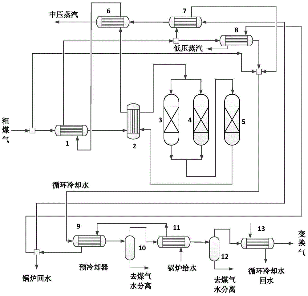
[0035] The system of the high-efficiency coal-to-natural gas conversion process system described in the present invention, such as figure 1 As shown, the system includes a crude gas preheater 1, a gas-gas heat exchanger 2, a pre-converter A3, a pre-converter B4, a main transformer 5, a medium-pressure steam boiler 6, a medium-pressure steam preheater 7, Low-pressure steam boiler 8, precooler 9, flash tank A10, intercooler 11, flash tank B12, final cooler 13.

[0036] According to the methanation plant for H 2 / CO requirements, part of the raw gas from the pressurized gasification device enters the conversion device, and part of the raw gas is directly sent to the mixer through a bypass. The crude gas entering the conversion device first enters the crude gas preheater 1, and after being preheated, the crude gas passes through the gas-gas heat exchanger 2 for heat exchange and enters the pre-converter A3 and pre-converter B4 for conversion reaction, and then enters the main con...

Embodiment 2

[0041] The specific implementation of the high-efficiency coal-to-natural gas conversion process system described in the present invention is as follows:

[0042] Entering the coal-to-natural gas transformation process system with an annual output of 4 billion cubic meters, the single-sequence processing capacity is 140467Nm 3 / h. The crude gas enters the conversion device at a temperature of 170-180°C, first enters the crude gas preheater 1, preheats the crude gas to 200-210°C, passes through the gas-gas heat exchanger 2 to raise the temperature of the crude gas to 305-315°C, and enters the preheater Transformer A3 and pre-shift furnace B4 carry out the shift reaction, the temperature of the shift gas exiting the pre-shift furnace A3 and pre-shift furnace B4 is 340-350°C, and enters the main shift furnace 5 for reaction, and the shift gas after the shift reaction is about 360°C to The gas-gas heat exchanger 2 exchanges heat with the incoming crude gas, and the transformed ga...


PUM


Abstract

The invention discloses a high-efficiency coal-to-natural-gas shift process system, belonging to the technical fields of energy sources and chemical industry. The process is a two-stage low-temperature sulfur-tolerant shift technique, and the catalyst is a cobalt-molybdenum CO sulfur-tolerant shift catalyst. The process system adopts a partial CO shift process, i.e., part of the raw gas enters a shift converter to react, and the rest goes through the by-pass. The raw gas is preheated, and sequentially enters a preshift converter and a main shift converter to perform the CO shift reaction. The high-temperature shift gas out of the main shift converter is used for preheating the raw gas and byproduct steam by using the gradient utilization principle, the low-temperature waste heat is used for supplying water to the preboiler, and shift gas with the temperature of lower than 60 DEG C is cooled by circulating cooling water. The advanced energy integration technique is adopted to implement the gradient utilization of the energy of the coal-to-natural-gas shift unit, thereby effectively enhancing the overall energy efficiency of the system.

Description

technical field [0001] The invention belongs to the technical field of energy and chemical industry, and in particular relates to a high-efficiency coal-to-natural gas conversion process system. Background technique [0002] As a country rich in coal, poor in oil, and low in gas, China has always occupied a major position in my country's energy efficiency consumption. However, as a clean energy, the consumption of natural gas is increasing year by year. From 2004 to 2014, the consumption of natural gas in my country has grown at an annual rate of 16%. By 2014, the annual consumption of natural gas has reached 180 billion m 3 . According to the State Council's "Energy Development Strategic Action Plan (2014-2020)", the proportion of natural gas in my country's primary energy consumption will increase to more than 10% by 2020, and the annual natural gas consumption will reach 300 billion to 360 billion cubic meters. At that time, the annual output of conventional natural gas...

Claims


Application Information

Patent Timeline
IPC IPC(8): C10L3/08C01B3/16
CPCC10L3/08C01B3/16Y02P20/129Y02P20/52Y02P20/10
Inventor 钱宇刘阳杨思宇萧鸿华
Owner SOUTH CHINA UNIV OF TECH
Learn More