
Optical wave heating non-metal blow-molded water tank electric water heater provided with water flow sensor with pressure reduction function

A technology of water flow sensor and light wave heating, which is applied to water heaters, fluid heaters, lighting and heating equipment, etc. It can solve problems such as water leakage, pressure explosion, and inability to automatically adjust the pressure of the water tank.

Inactive Publication Date: 2016-06-29
GUANGDONG SHUNDE GUANGSHENG ELECTRICAL APPLIANCE
View PDF10 Cites 0 Cited by
  • Summary
  • Abstract
  • Description
  • Claims
  • Application Information

AI Technical Summary

Problems solved by technology

[0002] At present, all household electric water heaters in the world, the water inlet pipe is connected to the water source, from the water inlet to the water tank, without installing other components, can not automatically adjust the pressure in the water tank, all adopt a pressure-bearing structure, and the rated pressure is generally 0.6 Mpa, the test pressure is 1.2Mpa; this kind of pressure will cause many difficult problems; for example, the heat expansion and contraction water tank will crack, leak, and explode under pressure, which is a problem in the world

Method used


Image

  • Optical wave heating non-metal blow-molded water tank electric water heater provided with water flow sensor with pressure reduction function
  • Optical wave heating non-metal blow-molded water tank electric water heater provided with water flow sensor with pressure reduction function
  • Optical wave heating non-metal blow-molded water tank electric water heater provided with water flow sensor with pressure reduction function

Examples


Embodiment Construction

[0014] Attached below Figures 1 to 8 In the accompanying drawings: shell 1, cold water inlet pipe 2, hot water outlet pipe 3, water flow sensor 4 with decompression function, controller 5, halogen tube heated by light wave or carbon fiber tube electric heating tube 6 ( Upper electric heating pipe 6-1, lower electric heating pipe 6-2), sealing and fixing point 7, water tank 8, water nozzle 9, temperature measuring or temperature limiting sensor installation pipe 10, flange 11, pressure relief valve 14, sewage outlet 15 1. Water flows through the water heating device 16, the metal or non-metal casing 17, the air 18, and the water 19.

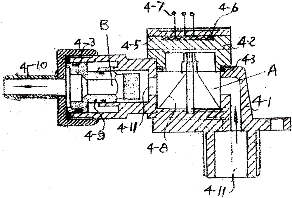
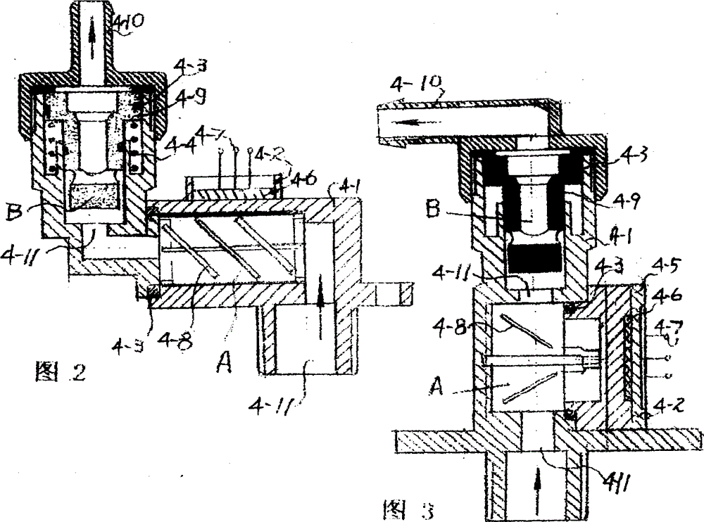
[0015] Figure 1 to Figure 3 It is a water flow sensor 4 with decompression function, which consists of a main body 4-1, a cover plate 4-2, a seal 4-3, a spring 4-4, an installation cover plate 4-5, an induction element 4-6, and a connection terminal 4 -7, impeller or rotor or Hall element 4-8, piston 4-9, interface 4-10, water inlet 4-11. The ...


PUM

PropertyMeasurementUnit
Lengthaaaaaaaaaa

Abstract

The invention provides an optical wave heating non-metal blow-molded water tank electric water heater provided with a water flow sensor with a pressure reduction function. A water tank 8 is made of non-metal materials through a blow molding technique. The water flow sensor 4 with the pressure reduction function is installed on a water inlet pipeline of the water tank. The water flow sensor is composed of a component A and a component B. According to the component A, when water flows, an impeller or a rotor or a Hall element 4-8 is pushed by water flow to rotate, pulse signals or current signals or voltage signals and the like are output by sensing the water flow rate, an intermediate relay is pulled in, and a circuit is closed; and when the water supply is cut off, water stops flowing, the circuit is opened, and an electric heating tube stops heating. According to the component B, a transverse through hole is formed in the small end of a piston 4-9, a through hole is further formed in the middle of the piston 4-9, when water inflows, and water passes through the transverse through hole and then enters the water tank through the middle hole of the piston 4-9; and when the water tank is filled with water or the water inlet amount is larger than the water outlet amount, the pressure in the water tank is increased, back pressure is generated by the big end of the piston 4-9, the piston is made to move, and accordingly the area of a water inlet 4-11 is decreased or even the water inlet 4-11 is closed.

Description

technical field [0001] The invention relates to a light wave heating non-metallic blow molding water tank electric water heater equipped with a water flow sensor with a decompression function. Background technique [0002] At present, all household electric water heaters in the world, the water inlet pipe is connected to the water source, from the water inlet to the water tank, without installing other components, can not automatically adjust the pressure in the water tank, all adopt a pressure-bearing structure, and the rated pressure is generally 0.6 Mpa, the test pressure is 1.2Mpa; this pressure will cause many difficult problems; for example, the heat expansion and contraction water tank will crack, leak, and explode under pressure, which is a problem in the world. Contents of the invention [0003] The present invention improves the existing electric water heater. After the improvement, it is a light wave heating non-metallic blow-molded water tank electric water hea...

Claims


Application Information

Patent Timeline
IPC IPC(8): F24H1/20F24H9/20
Inventor 刘运柳岑自健刘伶刘成
Owner GUANGDONG SHUNDE GUANGSHENG ELECTRICAL APPLIANCE
Learn More