A blowing and suction working device for rail sewage suction vehicles

A technology of working device and sewage suction truck, which is applied in track cleaning, construction, cleaning methods, etc., can solve the problems of ballast bed dust and iron filings pollution, achieve the effect of reasonable air flow direction, simple design, and improved operation effect

Active Publication Date: 2017-08-25
CRCC HIGH TECH EQUIP CORP LTD
View PDF8 Cites 0 Cited by
  • Summary
  • Abstract
  • Description
  • Claims
  • Application Information

AI Technical Summary

Problems solved by technology

[0004] The invention provides a blowing and suction working device for a rail sewage suction vehicle, which is used to blow up the dust and debris on the surface of the ballast bed and in the gaps of the ballast bed, and immediately suck it into the dust removal device of the sewage suction vehicle to solve the problem of ballast bed dust The pollution of iron filings ensures the safety of railway electrical equipment and traffic

Method used


Image

  • A blowing and suction working device for rail sewage suction vehicles
  • A blowing and suction working device for rail sewage suction vehicles
  • A blowing and suction working device for rail sewage suction vehicles

Examples


Embodiment 11

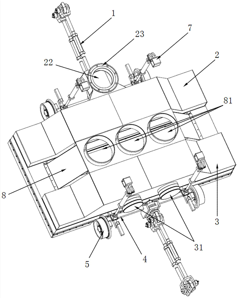
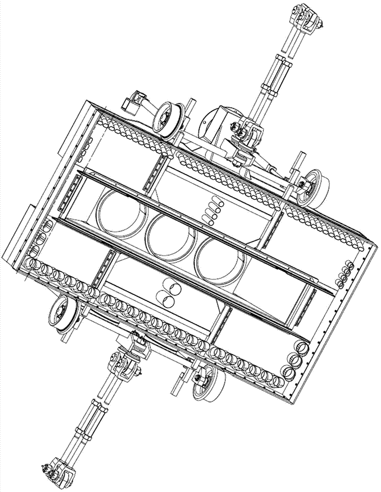
[0068] Embodiment 1.1: The blowing and sucking working device of rail sewage suction vehicle, such as figure 1 , figure 2 The blowing and suction working device for the track sewage suction vehicle provided in this embodiment includes:

[0069] The trolley frame 4, the trolley frame 4 is a flat cover type frame, and the front and rear sides of the flat cover type frame are respectively provided with two working wheels 5, which are used to fall on the rails and roll during operation;

[0070] The drawbars 1 installed on the front and rear sides of the trolley frame 4; one end of each drawbar 1 is connected to the center of the front / rear side of the sewage suction work trolley frame 4, and the other end of each drawbar 1 is connected to the track for sewage suction On the car body; the drawbar 1 is used for pulling the track sewage suction vehicle to walk with the sewage suction work trolley when the track sewage suction vehicle is walking.

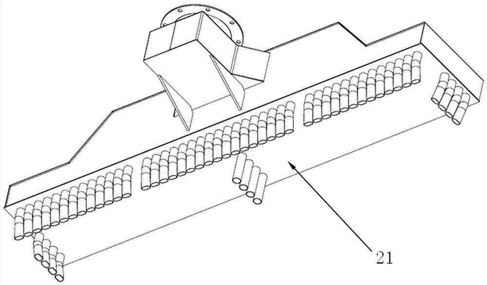
[0071] The front blowing box bod...

Embodiment 12

[0085] Embodiment 1.2: The blowing and sucking working device for rail sewage suction vehicles is the same as that of Embodiment 1.1, except that the bottom pipe diameter of the first blowing elbow of the front blowing box is 120mm.

Embodiment 13

[0086] Embodiment 1.3: The blowing and sucking working device for rail sewage suction vehicles is the same as that of Embodiment 1.2, except that the angle between the curved part of the head of the first blowing elbow and the bottom is 165° o .


PUM


Abstract

A blowing and suction work device for a rail suction-type sewer scavenger comprises a trolley frame, two air blowing boxes and an air suction box, wherein the front side and the rear side of the trolley frame are both provided with two work wheels; the two air blowing boxes are installed on the front side and the rear side of the sewer suction work trolley frame respectively; the air suction box is installed between the front air blowing box and the rear air blowing box.The front air blowing box is provided with a round front air inlet, the front air inlet is provided with a flange used for connecting the front air inlet with an air inlet pipeline of the blowing and suction work device, the rear side face of the rear air blowing box is provided with two round rear air inlets, a front air blowing nozzle assembly is arranged at the bottom of the front air blowing box, a rear air blowing nozzle assembly is arranged at the bottom of the rear air blowing box, an air suction opening is formed in the bottom of the air suction box, and a round air outlet is formed in the top of the air suction box; the front air blowing nozzle assembly and the rear air blowing nozzle assembly are distributed along the three faces of the bottom face edge of the air blowing box, air blowing airflow covers the transverse direction and the longitudinal direction of the cross section of a whole ballast bed, dust and cuttings of the whole cross section are blown into the air suction opening, accordingly the dust and the cuttings can be sucked in the scavenger more easily, and the sewer suction effect is improved.

Description

technical field [0001] The invention relates to the technical field of engineering equipment, in particular to a blowing and suction working device for a track sewage suction vehicle. Background technique [0002] With the great development of high-speed railways in recent years, high-speed railway lines have encountered the problem of ballast pollution before opening and during operation. Before the opening, it was difficult to clean construction dust, garbage and other dirt manually; after the opening, natural disasters such as sandstorms would pollute the ballast bed; the rails of the line need to be regularly polished or milled for maintenance, and the grinding left on the surface of the ballast bed during equipment operation The debris also brings pollution, and it is difficult to manually clean up the abrasive debris retained on the surface of the ballast bed. The pollution of the ballast bed has a great harm to the operation of high-speed railway trains. Taking the W...

Claims


Application Information

Patent Timeline
Patent Type & Authority Patents(China)
IPC IPC(8): E01H8/10
CPCE01H8/105
Inventor 郭关柱张继恩王磊卫明
Owner CRCC HIGH TECH EQUIP CORP LTD
Why Eureka
Try Eureka