
A special tool holder for deep and long hole circular inner groove boring

A special tool holder, deep and long hole technology, applied in the direction of the boring bar, etc., can solve the problems of poor axial dimension accuracy, aggravated tool wear, large cutting force, etc., to reduce cylindricity error, reduce force deformation, and improve machining The effect of precision

Inactive Publication Date: 2017-09-22
NANJING UNIV OF SCI & TECH
View PDF1 Cites 0 Cited by
  • Summary
  • Abstract
  • Description
  • Claims
  • Application Information

AI Technical Summary

Problems solved by technology

However, the radial dimension of this composite tool is large, and it cannot process deep and long holes with small diameters.
Moreover, the radial dimensions of the rough boring part and the rolling part are fixed, which can only be used for boring the inner wall of the deep hole, and cannot realize the boring processing of the annular inner groove of the multi-layer deep hole, and the processing object is relatively single
And the tool is not equipped with a corresponding chip removal structure, the chip is easy to scratch the machined surface, and it will also increase the tool wear and affect the tool life
[0005] Zhang Yanting of the Heavy Lathe Research Institute introduced a high-efficiency, high-precision grooving tool holder suitable for box hole processing in a paper titled "New Grooving Tool Holder Structure and Application". The oblique slider and the chute on the blade form a radial and reverse radial structure, which can reliably control the feeding and retracting of the tool, but the tool holder has only one blade, and the cutting radial force and tangential force cannot be offset, and there is no The corresponding guide support structure has poor rigidity of the cutter bar. In addition, if you want to process multi-layer annular grooves, you must rely on the adjustment nut to realize the axial position control. Chip structure, chips are easy to block in the cutter head, which seriously affects the machined surface quality and tool life
[0006] A paper titled "Design of Practical Processing Tools for Holes and Slots" by Lu Xiaobin introduced a special tool suitable for processing workpieces with holes and inner grooves in each hole. However, due to the fixed axial position of the positioning sleeve, if you want to process multi-layer annular grooves, you must use the knife row structure to process multiple inner grooves at the same time, and the cutting force is relatively large, and the tool only has One-sided guide rail, and the moment of inertia of the guide rail section is small, and the force deformation is large, which may easily lead to the loss of the tool
And the tool does not add corresponding guides and supports, the overall rigidity of the tool bar is weak, and it is not suitable for the processing of deep hole multi-layer annular inner grooves
[0007] It can be seen from the above that in the field of deep hole inner groove processing, the existing technical tool holder has weak rigidity, poor flexibility in axial position control, and it is difficult to process multi-layer annular grooves. The radial dimension of the composite tool is large, which is not suitable for Deep and long hole machining with small hole diameter
Moreover, most of the cutter bars lack the corresponding chip removal structure, the chips are easy to scratch the processing surface, affect the tool life, and the processing efficiency is difficult to guarantee

Method used


Image

  • A special tool holder for deep and long hole circular inner groove boring
  • A special tool holder for deep and long hole circular inner groove boring
  • A special tool holder for deep and long hole circular inner groove boring

Examples


Embodiment

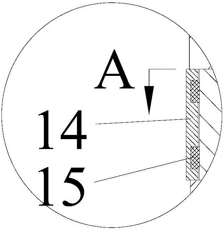
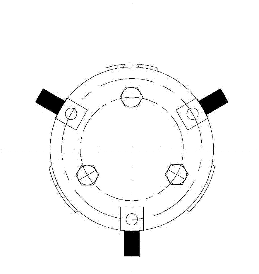
[0042] Such as figure 1 It is a schematic diagram of the longitudinal section of the segmented special boring bar for deep hole annular inner groove boring with guiding double supports of the present invention. It is mainly suitable for the boring process of small diameter deep long holes and deep long hole annular grooves. The length-to-diameter ratio of the boring bar is 17:1, and the diameter of the main body of the tool bar is 21mm. The boring bar is composed of a guide part, a cutter head part, a tool advance and retreat control part, an axial positioning part, an auxiliary support part and a rod body part. The guide part and the auxiliary support part provide support for the cutter head part, reducing stress deformation at the cutter head. The rear mandrel in the body section is made of a material with a high modulus of elasticity, which further increases the overall rigidity of the shank. The cutter head part is provided with three uniformly arranged blades, most of t...


PUM


Abstract

The invention discloses a special segmented boring bar with double guide support and used for boring machining for inner annular grooves of deep holes. The boring bar comprises a guide part, a cutter bit part, a cutter advancing-retreating control part, an axial location part, an auxiliary support part and a bar body part, wherein a guide head is connected with the front end of a sleeve by virtue of dowels, the auxiliary support part is connected with the sleeve by virtue of spherical screws, and due to the combination of the guide head and auxiliary support blocks, the partial static rigidity of the cutter bit can be greatly improved; a front baffle is connected with the front end of the guide head by virtue of a screw, and a rear baffle is connected with the rear end of the sleeve by virtue of a screw; and three uniformly-arranged blades are arranged in the peripheral direction of the cutter bit part, and capable of counteracting a radial force and a tangential force during cutting, and further improving the rigidity of the cutter bar. The special segmented boring bar with double guide support, which is disclosed by the invention, is applicable to boring machining for inner annular grooves of deep holes with large length-diameter ratios and multilayer deep holes; and compared with a boring bar in the prior art, the machining range is wider, and the machining surface quality and machining accuracy are remarkably improved.

Description

technical field [0001] The invention belongs to the field of deep hole inner groove processing, in particular to a special cutter bar for boring annular inner grooves of deep and long holes. Background technique [0002] In machining technology, deep hole annular inner groove is mainly realized by boring. However, in the process of boring the inner groove of the deep hole, the boring bar is in an overhanging state. Without guide support, the cutter head is not restrained, and the cutting force can easily deform the boring bar, and the structure of the tool bar The size is limited by the hole diameter of the workpiece, and the long-diameter ratio is relatively large (generally greater than 15), so the rigidity of the boring bar is weak, which is easy to cause the tool to give way, and the machining accuracy is difficult to guarantee. Moreover, in the process of deep hole boring, the cutting force is mostly uneven, the dynamic stiffness of the boring bar used for boring is po...

Claims


Application Information

Patent Timeline
Patent Type & Authority Patents(China)
IPC IPC(8): B23B29/02
CPCB23B29/02
Inventor 程寓付乾辰
Owner NANJING UNIV OF SCI & TECH
Learn More