Engine with oil filtering and cooling device

An oil cooling and engine technology, which is applied in the direction of machine/engine, engine components, engine cooling, etc., can solve the problems of complex structure of water-cooled oil cooler, increased load on oil pump, and difficulty in ensuring oil temperature, etc. , The effect of improving power and viscosity-temperature

Active Publication Date: 2016-06-22
CHONGQING LONGWANG ELECTROMECHANICAL
View PDF5 Cites 3 Cited by
  • Summary
  • Abstract
  • Description
  • Claims
  • Application Information

AI Technical Summary

Problems solved by technology

Thereby reducing frictional resistance, reducing power consumption, and reducing wear and tear of machine parts, so as to achieve the purpose of improving the reliability and durability of the engine. However, during the working process of the engine oil, the oil will become thinner due to the high temperature and reduce the lubricating ability. , this factor will cause the engine to fail to run normally because the lubrication effect cannot keep up. Therefore, the existing engine is usually equipped with an oil cooler in the lubricating oil circuit. However, the external oil cooler will cause the engine lubricating oil channel If the length is too long, it will greatly increase the load of the oil pump. On the other hand, the existing oil cooler is usually air-cooled or water-cooled; the air-cooled oil cooler is composed of many cooling tubes and cooling plates. , use the head-on wind of the car to cool the hot oil cooler core, the cooling effect of the air-cooled oil cooler is determined by the air volume of the cooling air, it is difficult to ensure that the oil is at a suitable temperature; the water-cooled oil cooler is placed in the cooling water circuit, using The temperature of the cooling water is used to control the temperature of the lubricating oil. When the temperature of the lubricating oil is high, it is cooled by the cooling water. When the engine starts, it absorbs heat from the cooling water to increase the temperature of the lubricating oil rapidly. The shell of the oil cooler is made of aluminum alloy Body, front cover, rear cover and copper core tube. In order to enhance cooling, the tube is equipped with cooling fins. The cooling water flows outside the tube, and the lubricating oil flows inside the tube. The two exchange heat. The structure of the water-cooled oil cooler is complex. , the manufacturing cost is high, and it is difficult to arrange it in motor vehicles with low cost and small space, such as motorcycles, tricycles and other small vehicles

Method used


Image

  • Engine with oil filtering and cooling device
  • Engine with oil filtering and cooling device
  • Engine with oil filtering and cooling device

Examples


Embodiment Construction

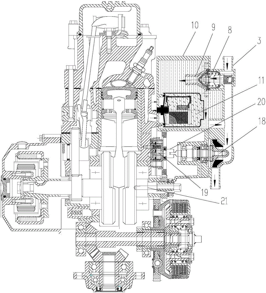
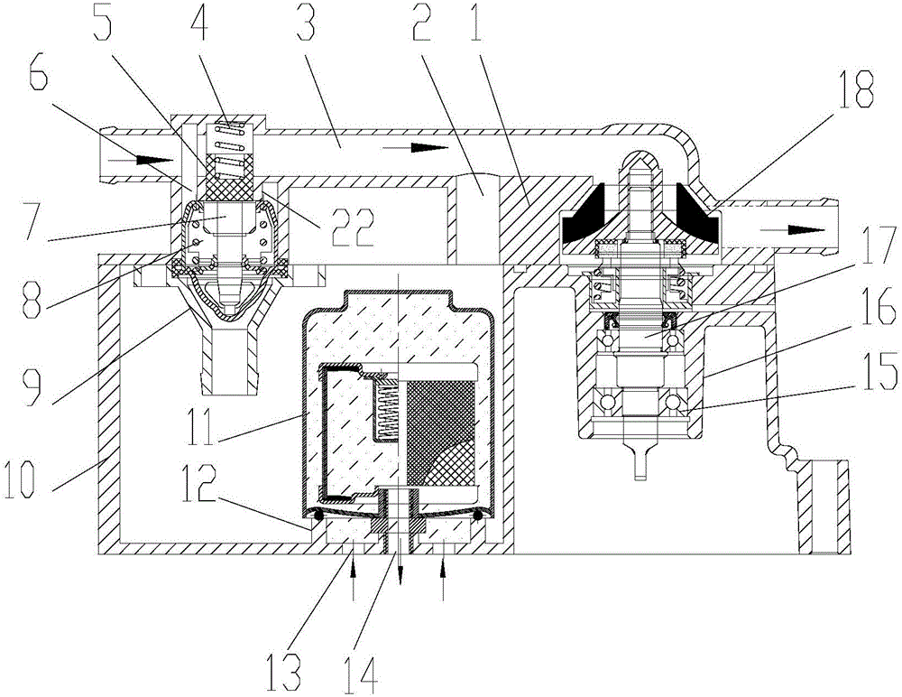
[0019] figure 1 It is a structural schematic diagram of the present invention; figure 2 It is a schematic diagram of the flow of cooling water in the closed state of the thermostat valve 8 of the present invention; image 3 It is a schematic diagram of the cooling water flow when the thermostat valve 8 of the present invention is opened, as shown in the figure: the engine with the oil filter cooler of the present embodiment includes the engine body and the cooling water passage 3 communicated with the water jacket of the engine body , an oil cooling water tank communicated with the cooling water channel 3 through a bypass, an oil filter 11 that is connected to the lubricating oil circuit of the engine body and arranged in the oil cooling water tank, and is used to control the entry of cooling water from the cooling water channel 3 The control valve of the oil cooling water tank; the engine with the oil filter cooler of the present embodiment, the oil filter is arranged in th...


PUM


Abstract

The invention discloses an engine with an oil filtering and cooling device. The engine comprises an engine body, a cooling water channel communicated with a water jacket of the engine body, an oil cooling water tank for accommodating cooling water from the engine body, an oil filter used for filtering oil in a lubricating oil channel of the engine body and arranged in the oil cooling water tank, and a control valve used for controlling cooling water to enter the oil cooling water tank from the cooling water channel. The engine can cool the oil filter by adopting the cooling water in a cooling system, so that the temperature of the oil is reduced; meanwhile, an external oil cooling channel is omitted, therefore, the load of an oil pump is reduced, the oil temperature is maintained, viscosity-temperature characteristics of the oil are effectively improved, and the lubricating effect of engine parts is further enhanced.

Description

technical field [0001] The invention relates to a power system of a motor vehicle, in particular to an engine with an engine oil filter cooler. Background technique [0002] The function of the engine lubrication system is to continuously deliver a sufficient amount of clean engine oil at an appropriate temperature to the friction surfaces of all transmission parts when the engine is working, and form an oil film between the friction surfaces to realize liquid friction. Thereby reducing frictional resistance, reducing power consumption, and reducing wear and tear of machine parts, so as to achieve the purpose of improving the reliability and durability of the engine. However, during the working process of the engine oil, the oil will become thinner due to the high temperature and reduce the lubricating ability. , this factor will cause the engine to fail to run normally because the lubrication effect cannot keep up. Therefore, the existing engine is usually equipped with an ...

Claims


Application Information

Patent Timeline
Patent Type & Authority Applications(China)
IPC IPC(8): F01M11/03F01M5/00F01P7/16
CPCF01M5/002F01M11/03F01P7/16F01P2025/40F01P2037/02F01P2050/22F01P2060/04
Inventor 王吉龙赵钢
Owner CHONGQING LONGWANG ELECTROMECHANICAL
Why Eureka
Try Eureka