
Automatic grouting hoop floating shoes

A technology of automatic grouting and floating hoop, which is used in earth-moving drilling, wellbore/well components, sealing/packing, etc. The size cannot be deformed, and the automatic current limiting cannot be realized, so as to avoid tube accidents, good sealing and good drillability.

Active Publication Date: 2017-05-10
京鸿石油钻采工程技术有限公司
View PDF5 Cites 0 Cited by
  • Summary
  • Abstract
  • Description
  • Claims
  • Application Information

AI Technical Summary

Problems solved by technology

[0005] 1. Unable to realize automatic current limiting: the material of the current limiting plate is mostly steel material, and the size of the diversion hole cannot be deformed to the required requirements during the mud circulation process, so the upward return flow rate, upward return speed and reverse direction of the mud in the annular space The current limit time cannot be controlled
[0006] 2. Most of the materials are steel pipe and steel plate structure, which has poor drillability, and the sealing surface is easily corroded when exposed to acidic environment, resulting in seal failure

Method used


Image

  • Automatic grouting hoop floating shoes
  • Automatic grouting hoop floating shoes
  • Automatic grouting hoop floating shoes

Examples


Embodiment Construction

[0026] Below in conjunction with accompanying drawing, floating hoop and floating shoes of the present invention are described in detail.

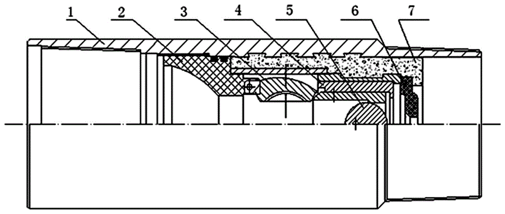
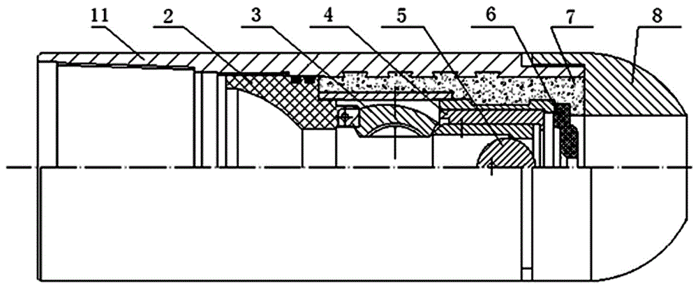
[0027] Such as figure 1 and figure 2 As shown, the floating hoop of the present invention includes a floating hoop body 1, a shut-off valve seat 2, a shut-off valve 3, a shear mechanism 4, an alloy ball 5 and a flow control valve 6, and the floating shoe of the present invention includes a floating shoe body 11, a shut-off valve seat 2 , cut-off valve 3, shearing mechanism 4, alloy ball 5, flow control valve 6 and guide cap 8, the present invention is processed with the casing circle that is connected with oil casing pipe on the upper and lower ends of the floating hoop body 1 and the upper end of the floating shoe body 11 The thread or casing partial trapezoidal thread, the lower end of the floating shoe body 11 is equipped with a guide cap 8, the inner wall of the floating hoop body 1 and the floating shoe body 11 is connected with a s...


PUM

PropertyMeasurementUnit
tensile strengthaaaaaaaaaa
brittleness temperatureaaaaaaaaaa

Abstract

The invention discloses an automatic grouting float collar and float shoe. Casing pipe threads are machined at the upper and lower ends of a float collar body (1) or the upper end of a float shoe body (1) and connected with petroleum casing pipes, a guiding cap is installed at the lower end of the float shoe body (1), a stop valve seat (2) is connected to the inner wall of the body (1) through a straight thread, an inclined surface is machined at an inner hole of the stop valve seat (2) as a sealing surface, a stop valve (3) is installed below the stop valve seat (2), the sealing face of a valve body is a spherical surface, a shearing mechanism (4) and a flow control valve (6) are fixedly connected to the portion, on the inner wall of the body (1), below the stop valve seat (2) through high-strength concrete (7) in a sealed mode, the flow control valve (6) is located below the shearing mechanism (4), and an alloy ball (5) is thrown into the shearing mechanism (4). In drilling operation, automatic grouting and automatic flow-limiting designing are performed, in this way, it is effectively avoided that in the process of lowering the casing pipes, surging pressure causes lost circulation, and the product is good in drillability, resistant to corrosion and good in well-cementation quality.

Description

technical field [0001] The invention relates to the technical field of petroleum tools, in particular to an automatic grouting floating hoop and a floating shoe used in the drilling process of petroleum and natural gas. Background technique [0002] As important casing accessories, floating hoops and floating shoes directly affect the quality of cementing. At present, the existing floating hoops and floating shoes are mainly composed of a body, a restrictor plate, a stop valve seat, an alloy ball, and a guide cap. [0003] The utility model patent of Chinese patent No. 03269873.9 discloses a floating hoop and a floating shoe with reverse flow restriction for automatic grouting. The upper and lower ends of the floating hoop body or the upper end of the floating shoe are processed with casing threads connected with the oil casing, and the floating shoe The lower end of the body is equipped with a hemispherical round cap (that is, the guide cap). The inner wall of the body is ...

Claims


Application Information

Patent Timeline
Patent Type & Authority Patents(China)
IPC IPC(8): E21B33/13E21B34/08C08L15/00C08L45/02C08K13/02C08K3/22C08K5/09C08K3/06
CPCC08L15/005C08L2201/08E21B33/13E21B34/08C08L45/02C08K13/02C08K2003/2296C08K5/09C08K3/06
Inventor 刘书京
Owner 京鸿石油钻采工程技术有限公司
Learn More