Image rendering method and apparatus
An image rendering and image technology, applied in the field of image processing, can solve problems such as difficult to ensure real-time rendering, and achieve the effect of small calculation and simple logic
- Summary
- Abstract
- Description
- Claims
- Application Information
AI Technical Summary
Problems solved by technology
Method used
Image
Examples
Embodiment 1
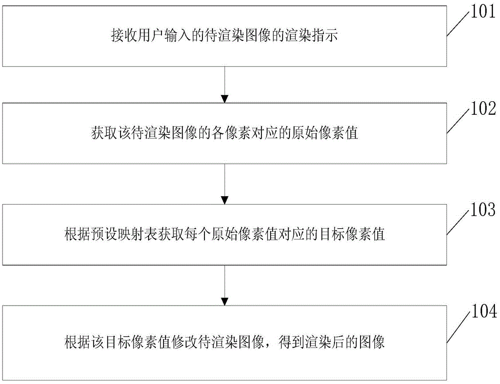
[0032] Such as figure 1 As shown, the embodiment of the present invention provides an image rendering method, including:
[0033] Step 101, receiving a rendering instruction of an image to be rendered input by a user.
[0034] In this embodiment, through the rendering instruction, the user may instruct to render a certain image, or may indicate what kind of rendering to perform on a certain image, which is not limited here.
[0035] Step 102, acquiring original pixel values corresponding to each pixel of the image to be rendered.
[0036] Step 103, obtain the target pixel value corresponding to each original pixel value according to the preset mapping table.
[0037] In this embodiment, since the pixel value of the image to be rendered has a specific value range, taking an 8-bit image as an example, the value range must be between 0-255; therefore, 0-255 needs to be set in the preset mapping table The target pixel value corresponding to the pixel value between; that is, t...
Embodiment 2
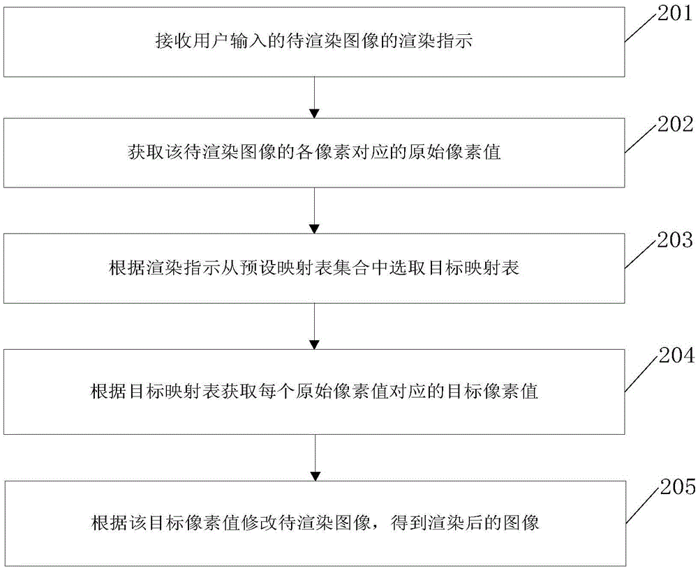
[0042] Such as figure 2 As shown, the image rendering method provided by the embodiment of the present invention includes:
[0043] Step 201, receiving a rendering instruction of an image to be rendered input by a user.
[0044] In this embodiment, through the rendering instruction, the user may instruct to render a certain image, or may indicate what kind of rendering to perform on a certain image, which is not limited here.
[0045] Step 202, acquiring original pixel values corresponding to each pixel of the image to be rendered.
[0046] Step 203, selecting the target mapping table from the preset mapping table set according to the rendering instruction.
[0047] In this embodiment, since the pixel value of the image to be rendered has a specific value range, taking an 8-bit image as an example, the value range must be between 0-255; therefore, the mapping table in the preset mapping table set only needs to be Just set the target pixel value corresponding to the pixel...
Embodiment 3
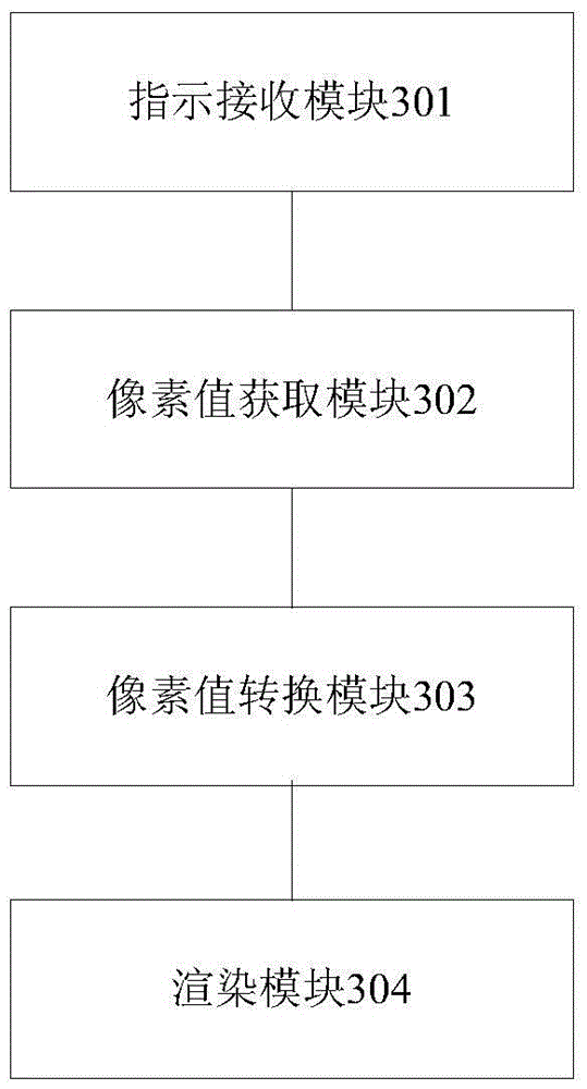
[0053] Such as image 3 As shown, an embodiment of the present invention provides an image rendering device, including:
[0054] An instruction receiving module 301, configured to receive a rendering instruction of an image to be rendered input by a user;
[0055] A pixel value acquisition module 302, connected to the indication receiving module, for acquiring the original pixel value corresponding to each pixel of the image to be rendered according to the rendering indication;
[0056] A pixel value conversion module 303, connected to the pixel value acquisition module, for acquiring a target pixel value corresponding to each original pixel value acquired by the pixel value acquisition module according to a preset mapping table;
[0057] The rendering module 304 is connected to the pixel value conversion module, and is used for modifying the image to be rendered according to the target pixel value obtained by the pixel value conversion module to obtain a rendered image.
[00...
PUM
 Abstract
Description
Claims
Application Information
 - R&D
- Intellectual Property
- Life Sciences
- Materials
- Tech Scout
- Unparalleled Data Quality
- Higher Quality Content
- 60% Fewer Hallucinations
Browse by: Latest US Patents, China's latest patents, Technical Efficacy Thesaurus, Application Domain, Technology Topic, Popular Technical Reports.
© 2025 PatSnap. All rights reserved.Legal|Privacy policy|Modern Slavery Act Transparency Statement|Sitemap|About US| Contact US: help@patsnap.com


