
Efficient energy supply system for indoor ski resort

A ski resort and energy supply technology, applied in the field of energy supply systems, can solve the problems of large power consumption and low efficiency of comprehensive energy utilization, achieve low electromagnetic pollution and noise pollution, improve power supply reliability, and reduce power transmission and transformation lines and the effect of the device

Inactive Publication Date: 2016-06-15
HUADIAN ELECTRIC POWER SCI INST CO LTD
View PDF6 Cites 2 Cited by
  • Summary
  • Abstract
  • Description
  • Claims
  • Application Information

AI Technical Summary

Problems solved by technology

At present, my country's indoor ski resorts still rely on electric energy for cooling, and use equipment such as screw compression refrigerators to obtain a low temperature of about -15°C, which consumes a lot of power and has low comprehensive utilization efficiency of energy.

Method used

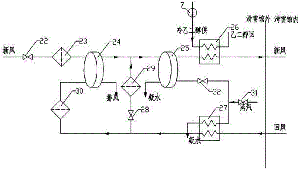
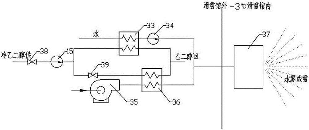

Image

  • Efficient energy supply system for indoor ski resort
  • Efficient energy supply system for indoor ski resort
  • Efficient energy supply system for indoor ski resort

Examples


Embodiment 1

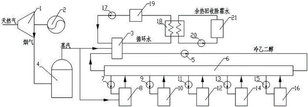
[0031] In this embodiment, the gas engine is a gas turbine 1 . like figure 1As shown, this embodiment consists of gas turbine 1, generator 2, ammonia-water absorption refrigeration equipment 3, waste heat boiler 4, ethylene glycol intermediate circulation pump 5, cold ethylene glycol device distributor 6, dehumidifier pump 7, fresh air Device 8, air cooler pump 9, air cooler unit 10, ground cooling pipe pump 11, ground cooling pipe device 12, cold storage pump 13, cold storage device 14, snow making cold pump 15, spray snow making device 16, water cooling heat exchanger 18, Water-cooled radiator 19, water-cooled circulation pump 17 are made up of defrosting water pump 20 and waste heat defrosting water device 21.

[0032] The gas turbine 1 drives the generator 2 to generate power for the ski resort. The flue gas outlet of the gas turbine 1 is connected to the waste heat boiler 4. The steam outlet of the waste heat boiler 4 is connected to the ammonia-water absorption refriger...

Embodiment 2

[0040] In this embodiment, the gas engine is an internal combustion engine 40, such as Figure 4 As shown, the present embodiment consists of internal combustion engine 40, generator 2, ammonia-water absorption refrigeration equipment 3, waste heat boiler 4, ethylene glycol intermediate circulation pump 5, cold ethylene glycol device distributor 6, dehumidifier pump 7, fresh air Device 8, air cooler pump 9, air cooler unit 10, ground cooling pipe pump 11, ground cooling pipe device 12, cold storage pump 13, cold storage device 14, snow making cold pump 15, ice and snow making device 41, water cooling heat exchanger 18 , water-cooled radiator 19, water-cooled circulating pump 17 and defrosting water pump 20 and waste heat defrosting water device 21 and form.

[0041] The internal combustion engine 40 drives the generator 2 to generate power for the ski resort. The flue gas outlet of the internal combustion engine 40 is connected to the ammonia-water absorption refrigeration equ...


PUM


Abstract

The invention relates to an efficient energy supply system for an indoor ski resort. The device comprises a gas engine, an electric generator, ammonia-water absorption refrigerating equipment, a waste heat boiler, a glycol middle circulating pump, a cold glycol device distributor, a dehumidifier pump, a fresh air device, an air cooler pump, a cooling unit, an earth cooling pipe pump, an earth cooling pipe device, a cool storage pump, a cool storage device, a snow making cold pump, a snow making device, a water cooling heat exchanger, a water cooling radiator, a water cooling circulating pump, a defrosting water pump and a waste heat defrosting water device. Exhaust waste heat of the gas engine is used for achieving cold, heat and electricity triplex cogeneration, the fresh air system with the heat recycling and dehumidifying functions recycles the cold amount of exhausted air and recycles heat energy generated by heat dissipation of the ammonia-water absorption refrigerating equipment for defrosting, the utilization rate of primary energy is improved while the requirement of a user of the ski resort is met, and the energy gradient utilization is achieved.

Description

technical field [0001] The invention relates to an energy supply system, in particular to an efficient energy supply system for indoor ski resorts. Background technique [0002] Skiing in our country is gradually becoming popular. In order to break through the limitations of regions and climates, indoor ski resorts have been built in many places. The loads of indoor ski resorts mainly include three categories: cooling, heating and electricity. Among them, the cooling load includes: enclosure structure heat dissipation, personnel heat dissipation, lighting heat dissipation, cooling for fresh air (dehumidification), cooling for snowmaking, heat dissipation for personnel transport equipment and snow maintenance equipment; heat load includes heat for rotary dehumidifiers, cooling fans Heat for defrosting; electrical loads include power consumption for lighting, personnel conveying equipment, snow maintenance equipment, and various pumps and fans. At present, my country's indoo...

Claims


Application Information

Patent Timeline
IPC IPC(8): F24F12/00F24F3/14F25B15/04F25B27/02F25B41/00F25B47/02F25C3/02F22B1/18F25B41/42
CPCF22B1/18F24F3/14F24F12/001F25B15/04F25B27/02F25B47/02F25C3/02F24F2003/144F24F2203/10F25B41/40Y02B30/625Y02A30/274
Inventor 韩海燕韩苗苗马军周宇昊阮炯明
Owner HUADIAN ELECTRIC POWER SCI INST CO LTD
Learn More