A low-pressure fan abrasive injection device and its application method

A low-pressure fan and jetting device technology, applied in abrasive feeding device, used abrasive processing device, abrasive and other directions, can solve the problems of high raw material cost, complex equipment structure, high process energy consumption, and achieve structural size design Reasonable, low abrasive crushing rate, safe and reliable operation

Active Publication Date: 2018-03-20
唐山金帝达机电有限公司
View PDF9 Cites 0 Cited by
  • Summary
  • Abstract
  • Description
  • Claims
  • Application Information

AI Technical Summary

Problems solved by technology

However, in the process of cleaning by pickling, on the one hand, the cost of raw materials is high, and on the other hand, the cleaning process has a greater impact on the environment; when using sandblasting equipment for cleaning, the existing technologies use air compressors as sand pellets. Jet power to form a high-speed jet beam to clean the above-mentioned pollutants on the surface of metal components and metal products
This process using an air compressor has high energy consumption, high noise, is not environmentally friendly, and is easy to damage the workpiece, especially for fine workpieces, with a high rejection rate. The compressed air itself contains water and oil, which is easy to cause contamination of the workpiece.
In addition, most of the current sandblasting equipment has defects such as large floor area, complex equipment structure, high operation and maintenance costs, poor sandblasting effect, repeated treatment, and low recycling of sand shot. In the open sandblasting operation, sand shot, pollutants, dust, etc. are discharged into the atmosphere together, which causes serious environmental pollution.

Method used


Image

  • A low-pressure fan abrasive injection device and its application method

Examples


Embodiment Construction

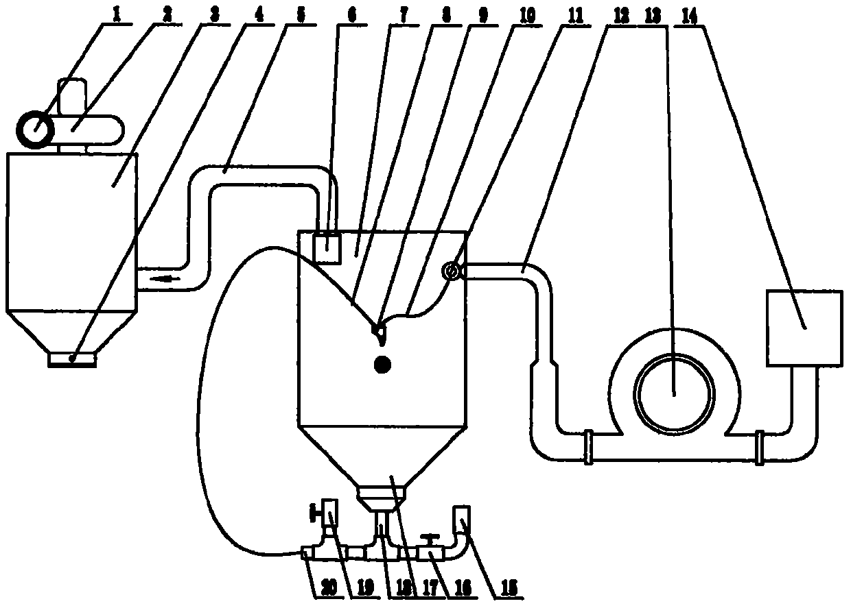
[0030] Attached below figure 1 The structure and usage method of the abrasive blasting device of the present invention will be described. A low-pressure blower abrasive injection device is provided with a dust remover, a working chamber, an abrasive supply device, an abrasive collector and an air supply device, the air supply device is a low-pressure blower fan 13, and a nozzle 9 is arranged in the working chamber 7. Spray head one end is provided with nozzle, and the other end communicates with air inlet pipe 10 and inlet abrasive material pipe 8, and the top of working chamber communicates with described deduster, and the bottom of working chamber communicates with described abrasive material collector 17, and described air inlet pipe communicates with described dust catcher. The low-pressure blower is communicated, and the abrasive material inlet pipe is communicated with the abrasive material supplier; the abrasive material supplier is communicated with the abrasive materi...


PUM


Abstract

The invention relates to an abrasive jetting device with a low pressure fan.A dust remover, a working chamber, an abrasive feeder, an abrasive collector and an air supply device are arranged.The abrasive jetting device is characterized in that the air supply device is the low pressure fan, a spray head is arranged in the working chamber, one end of the spray head is provided with a spray nozzle, the other end of the spray head is communicated with an air inlet pipe and an abrasive inlet pipe, the upper portion of the working chamber is communicated with the dust remover, the bottom of the working chamber is communicated with the abrasive collector, the air inlet pipe is communicated with the low pressure fan, and the abrasive inlet pipe is communicated with the abrasive feeder; the abrasive feeder is communicated with the abrasive collector through a filter screen.The abrasive jetting device is suitable for equipment for cleaning the surfaces of metal components and metal products and can effectively remove substances such as black skin, rusty spots and burrs on the metal surfaces, and the effects of enabling the surfaces of the metal products to be more smooth and cleaner and strengthening the hardness are achieved.The abrasive jetting device is also suitable for deburring of plastic and products thereof, coating stripping, carving of glass, stone and timber, machining and manufacturing of crafts and the like.An air compressor is not used, the device is particularly suitable for machining of exquisite workpieces, automatic control is achieved, and machining operation is convenient, rapid, efficient, safe, environmentally friendly and capable of saving materials and energy.

Description

technical field [0001] The invention relates to surface cleaning equipment for metal components and metal products, in particular to an abrasive spraying device and its use method, which can effectively remove black skin, rust, burrs and other substances on the metal surface by using the continuous working low-pressure spraying method of the device , to achieve the effect of smoother and harder surface of metal components and metal products. Moreover, automatic control is realized, and the processing operation is convenient, efficient, safe, environmentally friendly, material-saving, and energy-saving. Background technique [0002] During the processing and storage of metal components and metal products, oxides, rust, welding slag, black skin, burrs or other pollutants are often formed on the surface. In order to improve the service life and surface finish of metal components and metal products To meet the requirements of usability and aesthetics, conventional methods inclu...

Claims


Application Information

Patent Timeline
Patent Type & Authority Patents(China)
IPC IPC(8): B24C1/08B24C7/00B24C9/00
CPCB24C1/08B24C7/0046B24C7/0061B24C9/003B24C9/006
Inventor 窦川忠
Owner 唐山金帝达机电有限公司
Why Eureka
Try Eureka