
An adjustable dual-function spindle loose broach control device

A control device, dual-function technology, applied in positioning devices, manufacturing tools, clamping and other directions, can solve the problems of not being suitable for spindle testing of various sizes and specifications, and not having the function of loosening and broaching spindle testing, saving time, The effect of improving assembly efficiency

Active Publication Date: 2018-01-26
LUOYANG BEARING RES INST CO LTD
View PDF14 Cites 0 Cited by
  • Summary
  • Abstract
  • Description
  • Claims
  • Application Information

AI Technical Summary

Problems solved by technology

[0007] Existing spindle test devices are all aimed at the comprehensive performance indicators of ordinary rotary machine tool spindles, such as: the vibration, sealing, temperature rise, noise, thermal deformation and other performance tests of the spindle, and do not have the test for loose broach spindles Function
In addition, there are also some test devices that can realize the function of loosening the broach of the spindle, but this type of device is simply to realize that the count of the action of loosening the broach reaches the expected number of times before the spindle of a single specification is shipped out in batches; similar Due to the running-in process of ordinary spindles before leaving the factory, it is not suitable for testing spindles of various sizes and specifications

Method used


Image

  • An adjustable dual-function spindle loose broach control device
  • An adjustable dual-function spindle loose broach control device
  • An adjustable dual-function spindle loose broach control device

Examples


Embodiment Construction

[0026] The present invention will be further elaborated below in combination with specific embodiments.

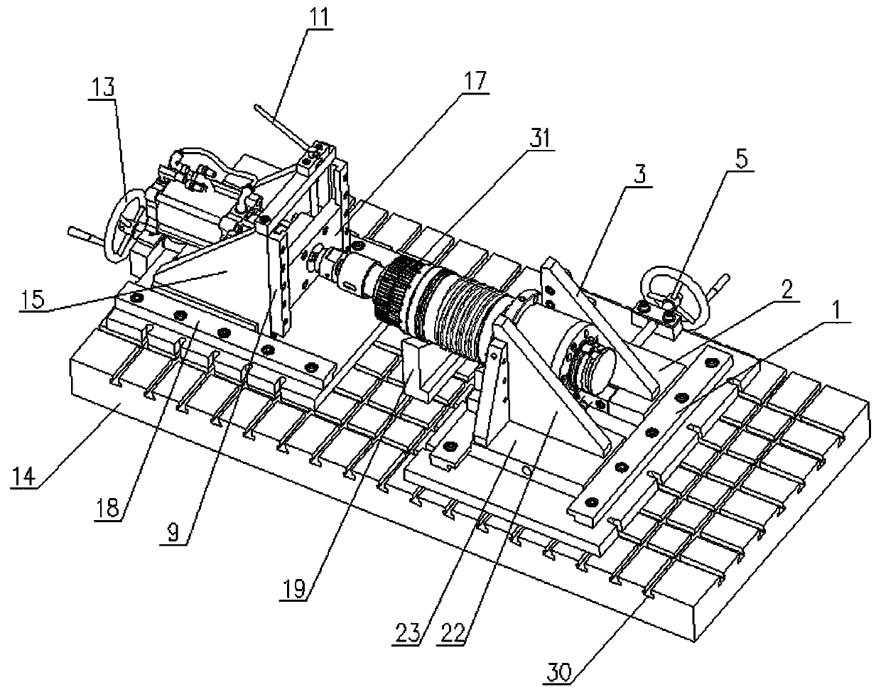
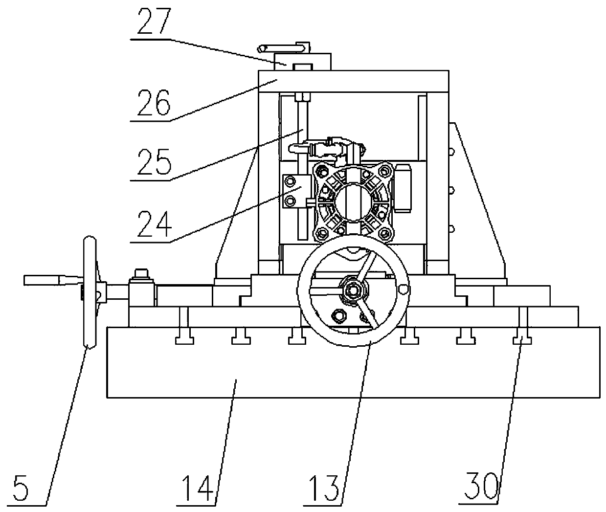
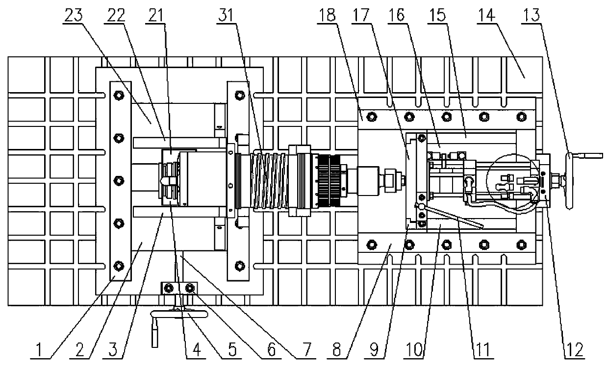
[0027] As shown in the figure: an adjustable dual-function spindle loose broach control device, including the spindle support of the machining center and the knife cylinder support fixed on the base platform 14 by bolts, it is characterized in that: the base platform 14 A plurality of equidistant T-slots 30 are arranged horizontally and vertically, and the bottoms of the spindle support of the machining center and the tool cylinder support are respectively provided with protrusions that match the T-slots 30, and can fit inside the T-slots 30. Sliding to adjust the relative position between the spindle support of the machining center and the tool cylinder support; the spindle support of the machining center is provided with a transverse guide rail, a transverse slider and a fixed spindle rib plate to radially position the spindles to be processed with different diameters , ...


PUM


Abstract

The invention relates to an adjustable dual-function spindle tool loosening and pulling control device. The adjustable dual-function spindle tool loosening and pulling control device comprises a machining center spindle support and an unclamping cylinder support which are fixed to a base platform. A plurality of T-type grooves are formed in the base platform in the transverse direction and the longitudinal direction. The bottom of the machining center spindle support and the bottom of the unclamping cylinder support are each provided with protrusions matched with the T-type grooves, and the protrusions can slide in the T-type grooves so as to adjust the relative positions of the machining center spindle support and the unclamping cylinder support. The machining center spindle support is provided with transverse guide rails, transverse sliding blocks and fixed spindle rib plates to carry out radial locating on to-be-machined spindles of different diameters, and the unclamping cylinder support is provided with longitudinal guide rails, a longitudinal sliding plate, air cylinder guide rails and an air cylinder supporting plate to carry out axial locating on the to-be-machined spindles of different diameters and lengths. The device is suitable for testing of spindle units of various diameters and meanwhile suitable for testing of rotary shaft components, wherein inner parts of the rotary shaft components are assembled, but the rotary shaft components are not mounted in spindle shells; and the device has the dual-function character.

Description

technical field [0001] The invention relates to the technical field of loosening and broaching control of the spindle of a CNC machining center, in particular to an adjustable dual-function spindle loosening and broaching control device. Background technique [0002] The spindle used in CNC machining center machine tools usually adopts a mechanism with automatic tool handle loosening. This mechanism can realize the automatic tool change function of the spindle system of the machine tool during processing, and then realize the numerical control of the machine tool. The assembled spindle is installed before leaving the factory. Difficulties are prone to occur in the determination of various performance indicators. [0003] Reasons for such difficulties include: [0004] 1. After the general machine tool spindle is assembled, it can be directly tested on the shaft extension part of the spindle, such as: the measurement of mechanical performance parameters such as radial runout...

Claims


Application Information

Patent Timeline
Patent Type & Authority Patents(China)
IPC IPC(8): B23Q3/155B23Q17/00
CPCB23Q3/155B23Q17/005
Inventor 王广辉李岩李彦雷树德李东亚李丽
Owner LUOYANG BEARING RES INST CO LTD
Learn More