Power transformer with magnetic core of silicon steel strip and its production method

A technology for power transformers and silicon steel strips, applied in transformer/inductor magnetic cores, transformer/inductor components, transformer/reactor installation/support/suspension, etc., can solve high cost, high-performance transformer production process complexity, etc. problems, to achieve the effect of eliminating internal stress, improving secondary recrystallization ability, and refining magnetic domains

Active Publication Date: 2017-08-25
蒋栖瑞
View PDF1 Cites 0 Cited by
  • Summary
  • Abstract
  • Description
  • Claims
  • Application Information

AI Technical Summary

Problems solved by technology

[0007] The technical problem to be solved by the present invention is to avoid the disadvantages of complex production process and high cost of the high-performance transformer in the prior art, and propose a high-performance through-wound magnetic core power transformer structure with simple production process and low cost and its production method

Method used


Image

  • Power transformer with magnetic core of silicon steel strip and its production method
  • Power transformer with magnetic core of silicon steel strip and its production method
  • Power transformer with magnetic core of silicon steel strip and its production method

Examples


Embodiment Construction

[0046] Embodiments of the present invention will be described in further detail below in conjunction with the accompanying drawings.

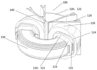
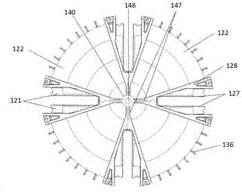
[0047] Such as Figures 1 to 11 In the preferred embodiment of the winding-magnetic core module 100 shown in the present invention, it includes at least two winding assemblies 120; each winding assembly 120 includes inner and outer windings 121, 122 nested together on a common axis; The inner and outer layer windings 121, 122 include inner and outer layer porcelain skeletons 123, 124, and inner and outer layer coils 125, 125 and outer layer coils 125 made of glass fiber insulated copper wire wound on the inner and outer layer porcelain skeletons 123, 124 respectively. 126; the cavities 131, 132 in the central part of the cross-section of the inner and outer windings 121, 122 are approximately rectangular, and are used to accommodate the silicon steel strips that are wound around and allow the two windings 121, 122 to overlap; the windings - Th...


PUM


Abstract

The invention provides a power transformer with a magnetic core formed by threading and winding a silicon strip and is suitable for the capacity ranging from 30 kVA to 1600 kVA. The power transformer at least comprises a winding, a magnetic core module and an insulating bearing device. The module further comprises at least two winding assemblies. Each winding assembly comprises an inner winding and an outer winding, wherein the inner winding and the outer winding are sleeved and stacked together in the mode of sharing one mean axis and formed by winding glass fiber insulated copper wires around an inner ceramic skeleton and an outer ceramic skeleton respectively. The center axes of inner cavities of all the winding assemblies are connected end to end to form a ring shape and are located to a special machine tool. The silicon strip is plugged into the cavities in a threading and winding mode to form the magnetic core. The inner windings and the outer windings wrap the threading and winding magnetic core; the whole magnetic core is annealed at the temperature ranging from 750 DEG C-800 DEG C and then dipped with inflame-retardant paint and baked to manufacture the winding magnetic core module, and the insulating bearing device is installed on the magnetic core module to form the transformer with the threaded and wound magnetic core, under the circumstance of the similar materials, compared with a tailored lamination magnetic core transformer in the prior art, materials and work hours are saved greatly, and power transformation efficiency is improved; the size is smaller, the weight is lower, magnetic core flux leakage is smaller, and operating noise is lower.

Description

technical field [0001] The present invention relates to 30 to 1600 kVA (kilovolt-ampere) medium-capacity single-phase and three-phase power transformers and their manufacturing methods, especially involves making windings first, placing them on a special machine tool and winding silicon steel strips to form a magnetic core, and then implementing 750 ℃ to 800 ℃ overall annealing process. Background technique [0002] Power transformers in the prior art, whether oil-immersed or dry-type, must be cut or stamped with silicon steel sheets of many sizes, laminated to form a cylinder with a circular cross-sectional envelope line, and then assembled into an iron core structure. The process is numerous and complicated, and there is a lot of material waste, and the transformer made has large magnetic flux leakage and low power transformation efficiency. [0003] For a long time, people have been trying to find a new power transformer structure and process method, but the results are...

Claims


Application Information

Patent Timeline
Patent Type & Authority Patents(China)
IPC IPC(8): H01F27/30H01F27/28H01F27/25H01F27/32H01F27/06H01F41/08
CPCH01F27/06H01F27/25H01F27/2828H01F27/306H01F27/327H01F41/08H01F2027/2833
Inventor 蒋栖瑞
Owner 蒋栖瑞
Why Eureka
Try Eureka