
Dual-seal chamber liquid state waterproof buried type energy saving transformer

An energy-saving transformer and waterproof technology, which is applied in the direction of transformer/inductor cooling, transformer/inductor coil/winding/connection, etc., can solve the problems of transformer operation safety hazards, loss of drainage function, corrosion of box shell, etc., to reduce No-load current, reduce no-load energy consumption, and ensure safe operation

Inactive Publication Date: 2016-06-08
刘洋
View PDF5 Cites 0 Cited by
  • Summary
  • Abstract
  • Description
  • Claims
  • Application Information

AI Technical Summary

Problems solved by technology

[0007] At present, the widely used buried transformers mostly use oil-immersed transformers, and the shell of the oil-immersed transformers is used to achieve the purpose of anti-leakage and waterproof. However, there are the following types of problems in actual operation: the high voltage of many buried transformers The connection method adopts the detachable connector (plug head) used in the ordinary European or American outdoor cable branch box to connect, and the sealing is not enough; the box body of most buried transformers has not been treated with special acid Long-term operation in an underground humid environment will corrode the box shell, which will lead to potential safety hazards in power operation; many buried transformers themselves do not have the function of underground operation, and can only rely on the foundation, foundation, and pit cover to be fully sealed. Waterproof and moisture-proof. Once the cover plate is damaged, water or moisture intrusion will cause hidden dangers in power operation; the operation of many buried transformers depends on the foundation, foundation, and built-in suction pumps in the corners of pits to drain water. If the situation is poured into the underground foundation, the excretion function will be lost, which will lead to potential safety hazards in the operation of the transformer; the high-voltage connection method of many buried transformers adopts the traditional silicone rubber soft connection method to be exposed in the pit, which cannot effectively prevent small animals and external mechanical forces damage, thereby increasing the safety hazard of power operation

Method used


Image

  • Dual-seal chamber liquid state waterproof buried type energy saving transformer
  • Dual-seal chamber liquid state waterproof buried type energy saving transformer

Examples


Embodiment Construction

[0032] In order to make the object, technical solution and advantages of the present invention more clear, the present invention will be further described in detail below in conjunction with the accompanying drawings and embodiments. It should be understood that the specific embodiments described here are only used to explain the present invention, and should not be used to limit the protection scope of the present invention.

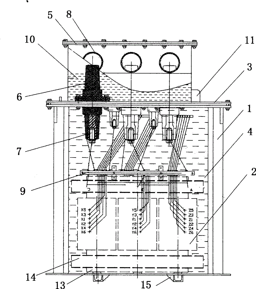
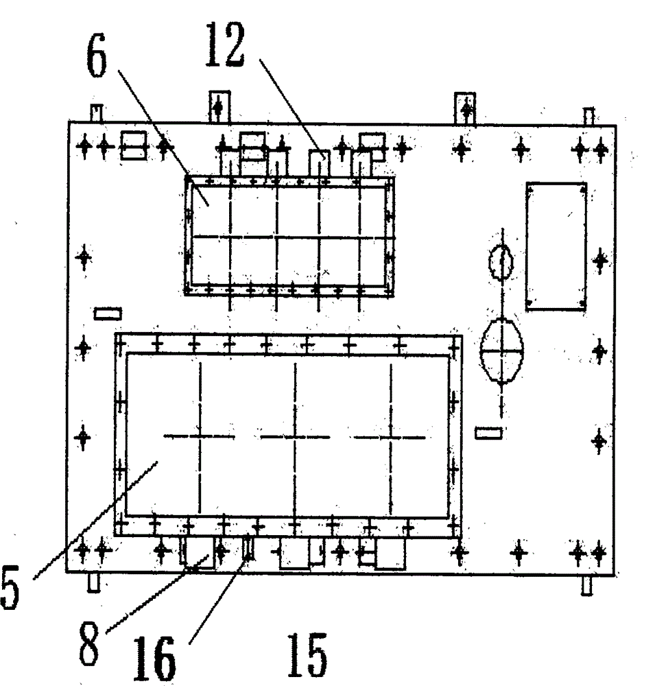
[0033] attached figure 1An overall plan view of the present invention is given in the accompanying figure 2 Provided in the plan view of the present invention, it can be seen that:

[0034] A liquid waterproof underground energy-saving transformer with double sealed chambers, including an oil tank 1, a transformer core 2 and a cover plate 3, the oil tank 1 is filled with transformer oil 4, the transformer core 2 is immersed in the oil tank 1, the top of the oil tank 1 and the cover plate 3. Connected by fastening bolts, it also includes the high-pres...


PUM


Abstract

The invention discloses a dual-seal chamber liquid state waterproof buried type energy saving transformer comprising a fuel tank, a transformer core and a cover plate; the fuel tank is filled with transformer oil; the transformer core is immersed in the fuel tank; the top of the fuel tank is connected with the cover plate through fastening bolts; the transformer also comprises a high voltage side sealing chamber, a low voltage side sealing chamber, a high voltage cable insulation sealing device, and a low voltage cable insulation sealing device; the high voltage side sealing chamber and the lower voltage side sealing chamber are arranged on the cover plate, respectively sealed with the surface of the cover plate, and fully filled with high density waterproof insulation molecules. The dual-seal chamber liquid state waterproof buried type energy saving transformer is simple and compact in structure, low in production cost, employs dual-sealing chamber for sealing, and the high-low voltage side sealing chambers and high-low voltage cable insulation sealing devices can commonly seal the low voltage cables; the transformer is dustproof, machinery outer force resistant, animal destroy resistant, so the whole product can be fully covered by metal, thus better ensuring the product to safely operate in water.

Description

technical field [0001] The present invention relates to the field of power equipment, more specifically to a double-sealed chamber liquid waterproof type buried energy-saving transformer. Background technique [0002] The power transmission and distribution and control equipment manufacturing industry is a national advanced manufacturing industry and a high-tech industry, supported by a number of national policies. "The Outline of the Twelfth Five-Year Plan for National Economic and Social Development of the People's Republic of China" Chapter 11 Promoting the Reform of Energy Production and Utilization Mode Section 3 Strengthening the Construction of Energy Transmission Channels: Adapting to Large-Scale Cross-regional Power Transmission and New Energy Power Generation To meet the requirements of grid connection, accelerate the construction of a modern power grid system, further expand the scale of west-to-east power transmission, improve regional backbone power grids, devel...

Claims


Application Information

Patent Timeline
IPC IPC(8): H01F27/30H01F27/32H01F27/14
Inventor 刘洋
Owner 刘洋
Learn More