
Polished shaft quenching machine tool for injection molding machine

A technology for quenching machine tools and injection molding machines, which is applied to quenching devices, furnace types, furnaces, etc., and can solve problems such as waste of loading and unloading actions of vertical machine tools, increased costs, and insufficient long-axis travel.

Pending Publication Date: 2021-06-08
太原市新明机械股份有限公司
View PDF0 Cites 0 Cited by
  • Summary
  • Abstract
  • Description
  • Claims
  • Application Information

AI Technical Summary

Problems solved by technology

[0002]In the current field of induction heating surface treatment, vertical machine tools can be fully quenched or partially quenched due to their good adaptability, strong versatility and flexible processing. The mainstream of machine tools, but in the induction hardening with uniform specifications and long optical axis, the vertical machine tool has the disadvantages of wasteful loading and unloading actions and insufficient long-axis travel; Disadvantages such as continuous quenching and action waste, continuous quenching machine tools designed by individual manufacturers also have disadvantages such as large quenching deformation, and additional alignment mechanisms need to be installed to increase costs

Method used


Image

  • Polished shaft quenching machine tool for injection molding machine
  • Polished shaft quenching machine tool for injection molding machine
  • Polished shaft quenching machine tool for injection molding machine

Examples


Embodiment

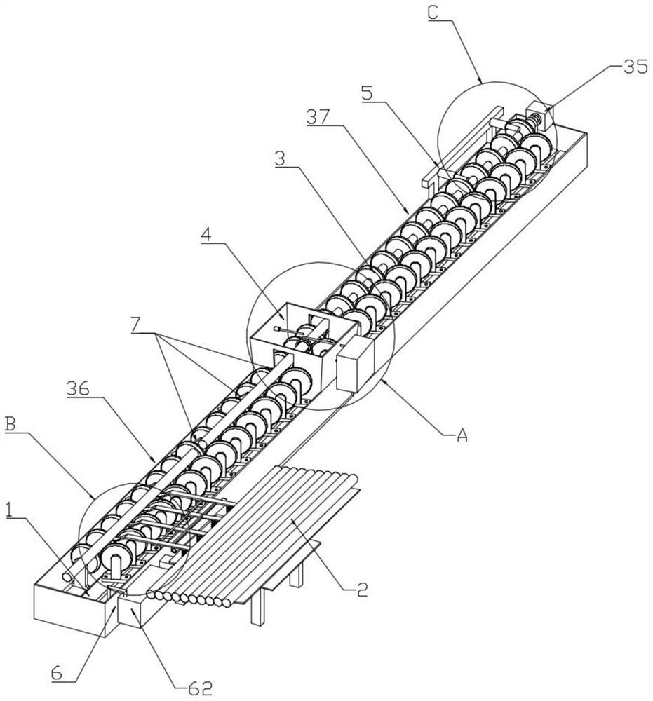
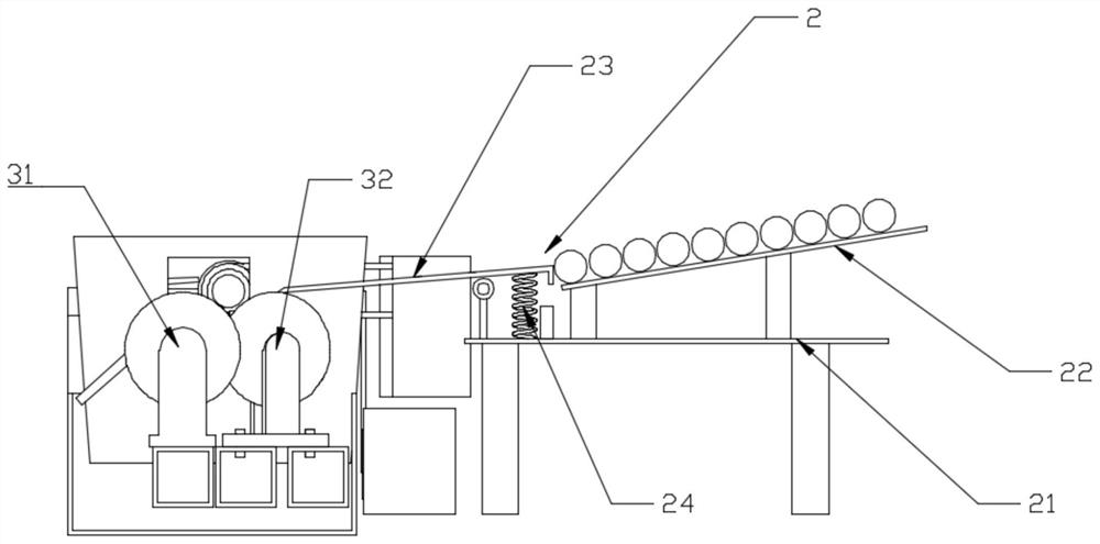
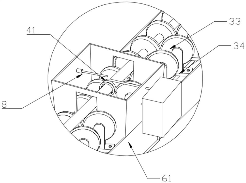
[0031] Such as Figure 1 to Figure 7 As shown, an optical axis quenching machine tool for an injection molding machine includes a support mechanism 1, a feeding mechanism 2, a conveying mechanism 3, a quenching mechanism 4, a blanking mechanism 5 and a local quenching adjustment mechanism; the conveying mechanism 3 is arranged on The upper end of the supporting mechanism 1, the feeding mechanism 3 includes a feeding mechanism 36 and a discharging mechanism 37 arranged in a straight line, the feeding mechanism 2 and the unloading mechanism 5 are respectively arranged at two ends of the feeding mechanism 3, and the quenching mechanism 4 It is arranged between the feeding mechanism 36 and the discharging mechanism 37;

[0032] Feeding mechanism 36 and discharging mechanism 37 all comprise driving wheel set 31 and passive wheel set 32, and driving wheel set 31 and passive wheel set 32 ​​are arranged in the same direction, and driving wheel set 31 is a straight wheel, and driven wh...


PUM


Abstract

The invention relates to the technical field of surface quenching, in particular to a polished shaft quenching machine tool for an injection molding machine. The polished shaft quenching machine tool comprises a supporting mechanism, a feeding mechanism, a conveying mechanism, a quenching mechanism and a discharging mechanism. The conveying mechanism is fixedly arranged at the upper end of the supporting mechanism, the feeding mechanism and the discharging mechanism are arranged at the two ends of the conveying mechanism respectively, and the quenching mechanism is arranged in the middle of the conveying mechanism. The conveying mechanism comprises a driving wheel set and a driven wheel set which are arranged in the same direction, the driving wheel set comprises straight wheels, the driven wheel set comprises angled side wheels and driven wheel seats, an included angle is formed between the angled side wheels and the driving wheel set, a polished shaft to be quenched is arranged above the driving wheel set and the driven wheel set, and one end of the driving wheel set is connected with a driving motor. The quenching mechanism comprises a heating sensor, and the heating sensor is arranged on the motion path of the polished shaft to be quenched. The polished shaft quenching machine tool can achieve continuous feeding, and is high in production efficiency, low in no-load energy consumption and waste and high in economical efficiency.

Description

technical field [0001] The invention relates to the technical field of surface quenching, and more specifically relates to an optical axis quenching machine tool for an injection molding machine. Background technique [0002] In the current field of induction heating surface treatment, vertical machine tools are the mainstream of induction machine tools due to their good adaptability, strong versatility, and flexible processing. They can be fully quenched or partially quenched. During quenching, vertical machine tools have disadvantages such as wasteful loading and unloading actions, and insufficient long-axis travel; ordinary horizontal machine tools are driven by a re-entry mechanism, which has disadvantages such as inability to continuously quench and wasteful actions, and continuous quenching machine tools designed by individual manufacturers There are also disadvantages such as large quenching deformation, and an additional straightening mechanism needs to be installed ...

Claims


Application Information

Patent Timeline
Patent Type & Authority Applications(China)
IPC IPC(8): C21D1/667C21D1/10C21D9/28C21D11/00
CPCC21D1/667C21D9/0018C21D9/0062C21D9/28C21D1/10C21D11/00C21D2221/00Y02P10/25
Inventor 窦志林刘威刘焕明崔恒王杰李海滨
Owner 太原市新明机械股份有限公司
Learn More