Plate-fin heat exchanger capable of being used for floating platform

A technology of plate-fin heat exchanger and floating platform, which is applied in the direction of heat exchanger type, heat exchanger shell, indirect heat exchanger, etc. Affect the heat exchange effect of the device and other problems, to achieve the effect of enhancing the anti-shake performance, increasing the medium processing capacity, and saving the amount of refrigerant

Active Publication Date: 2016-06-08
CHINA NAT OFFSHORE OIL CORP +1
View PDF5 Cites 7 Cited by
  • Summary
  • Abstract
  • Description
  • Claims
  • Application Information

AI Technical Summary

Problems solved by technology

However, before the refrigerant is filled into the shell, it needs to be throttled by the throttle valve. During the throttling process, part of the refrigerant is vaporized, and the refrigerant flows directly to the bottom of the shell after flowing into the shell, which is not conducive to the separation of the gas and liquid phases of the refrigerant. , leading to the entrainment of gaseous medium in the plate-fin flow channel at the bottom of the heat exchanger, which affects the heat exchange effect of the device; and in the initial stage of refrigerant filling, a large amount of liquid refrigerant pours directly to the bottom of the shell, which easily leads to equipment damage. shortened service life
[0004] In addition, in the prior art, the fluid flow in the plate-fin heat exchanger is sensitive to sloshing conditions, and its anti-sloshing performance is poor, so it is not suitable for liquefaction of natural gas on floating platforms; and one heat exchanger can only cool one medium, when the processing capacity of the cooled medium is large, the structure of the heat exchanger needs to be designed to be relatively large, and at the same time, the amount of refrigerant storage needs to be increased, which is not economical

Method used


Image

  • Plate-fin heat exchanger capable of being used for floating platform
  • Plate-fin heat exchanger capable of being used for floating platform
  • Plate-fin heat exchanger capable of being used for floating platform

Examples


Embodiment Construction

[0022] The present invention will be described in detail below in conjunction with the accompanying drawings and embodiments.

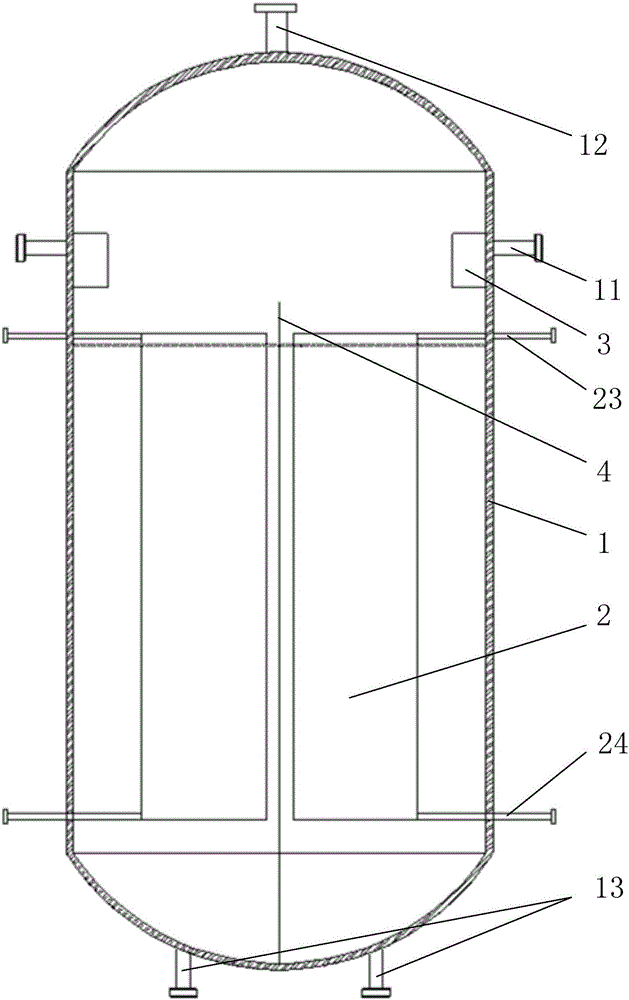
[0023] Such as figure 1 , figure 2 and image 3 As shown, a plate-fin heat exchanger applicable to a floating platform according to the present invention includes a shell 1 , at least one core 2 and at least one refrigerant distributor 3 . Wherein, at least one refrigerant inlet 11 is arranged on the upper part of the side wall of the shell 1, a gas phase refrigerant outlet 12 is arranged on the top, and at least one liquid phase refrigerant outlet 13 is arranged on the bottom, and the refrigerant inlet 11 and the liquid phase refrigerant outlet The number of 13 is the same as the number of cores 2 .

[0024] Such as Figure 4 ~ Figure 8 As shown, the core body 2 is arranged in the housing 1 and is located below the refrigerant inlet 11, and each core body 2 corresponds to each refrigerant inlet 11 and liquid-phase refrigerant outlet 13 one by on...


PUM


Abstract

The invention relates to a plate-fin heat exchanger capable of being used for a floating platform. The heat exchanger comprises a shell, at least one refrigerant even distributor and at least one core, wherein the refrigerant even distributors and the cores are arranged in the shell. At least one refrigerant inlet is formed in the upper portions of the side walls of the shell, a gas phase refrigerant outlet is formed in the top of the shell, and at least one liquid phase refrigerant outlet is formed in the bottom of the shell. The number of the refrigerant inlets, the number of the liquid phase refrigerant outlets and the number of the refrigerant even distributors are the same as the number of the cores. The cores are in one-to-one correspondence to the refrigerant inlets, the refrigerant even distributors and the liquid phase refrigerant outlets. The refrigerant even distributors are connected with the refrigerant inlets. The cores are located below the refrigerant inlets and the refrigerant even distributors. Each core comprises an inner runner, an outer runner, inlet pipes and outlet pipes. Each inner runner is divided into multiple layers, identical or different kinds of cooled media can flow in the different layers of each inner runner, and the multiple layers of each inner runner where the identical kind of cooled media flow share one corresponding inlet pipe and outlet pipe. The inlet pipes and the outlet pipes penetrate the shell to stretch to the outside. The outer runners communicate with the shell.

Description

technical field [0001] The invention relates to a plate-fin heat exchanger, in particular to a plate-fin heat exchanger which can be used for a floating platform. Background technique [0002] The technology of plate-fin heat exchanger is mature, and it has been widely used in the field of small-scale natural gas liquefaction. During the liquefaction process, natural gas and hot refrigerant usually flow through the flow channel of the heat exchanger from top to bottom, while cold refrigerant flows back from bottom to top to exchange heat with natural gas and hot refrigerant. The liquid phase of the cold flow refrigerant has a large pressure drop in the plate-fin flow channel, and it mainly relies on the entrainment of the gas phase to flow upward. When the operating conditions change, it is very easy for the gas phase to not completely entrain the liquid phase, resulting in liquid phase cooling. The liquid refrigerant accumulates at the bottom of the cold box, affecting the...

Claims


Application Information

Patent Timeline
Patent Type & Authority Applications(China)
IPC IPC(8): F28D9/00F28F3/02F28F9/22
CPCF28D9/00F28F3/022F28F9/22
Inventor 陈杰李秋英尹全森花亦怀常心洁张晓慧
Owner CHINA NAT OFFSHORE OIL CORP
Why Eureka
Try Eureka