
Automatic-control valve control circuit

A technology of control circuit and self-control valve, applied in valve details, valve device, valve operation/release device, etc., can solve the problems of low reliability, poor accuracy, simple and rough control, etc., to ensure stability, improve accuracy, Guaranteed effect of reliability

Active Publication Date: 2016-06-01
陕西省电子技术研究所有限公司
View PDF5 Cites 4 Cited by
  • Summary
  • Abstract
  • Description
  • Claims
  • Application Information

AI Technical Summary

Problems solved by technology

Due to the harmonic interference generated when the self-control valve is working, it will have a greater impact on the internal resonant circuit and the input low-frequency square wave signal, so that the self-control valve is always in an oscillating state, with poor precision, simple and rough control, and low reliability.

Method used


Image

  • Automatic-control valve control circuit
  • Automatic-control valve control circuit
  • Automatic-control valve control circuit

Examples


Embodiment Construction

[0041] The implementation of the present invention will be described in detail below in conjunction with the drawings and examples.

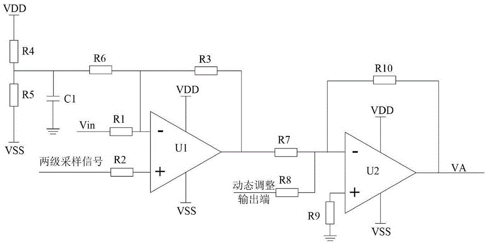
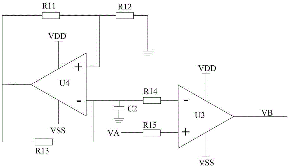
[0042] Such as figure 1 As shown, the present invention is a self-control valve control circuit, including an input zeroing circuit, a voltage comparator circuit, an error amplifier circuit, a gain amplifier circuit, a buffer amplifier circuit, an H-bridge drive circuit, a two-stage sampling circuit and a dynamic adjustment circuit.

[0043] The initial input signal of the present invention is generally a TTL square wave signal or a sine wave signal, which interacts with the feedback signal in the rear-stage sampling circuit and the dynamic adjustment circuit, and is input into the input zero-adjustment circuit to eliminate the error caused by the operation of the rear-stage automatic control valve The generated reverse electromotive force interferes with the input signal of the previous stage.

[0044] The input zeroing circuit is mainly compo...


PUM


Abstract

The invention discloses an automatic-control valve control circuit. The automatic-control valve control circuit comprises an input zeroing circuit, a voltage comparator circuit, an error amplifier circuit, a gain amplifier circuit, a buffer amplifier circuit, an H bridge drive circuit, a two-stage sampling circuit and a dynamic regulating circuit. According to the automatic-control valve control circuit, based on the original circuit, the dynamic relating circuit, the zeroing circuit and the two-stage speed detecting circuit when an automatic-control valve works are additionally arranged, so that influence of an internal resonance circuit to an input low-frequency square wave signal when the automatic-control valve works is eliminated, dynamic regulating and automatic tracking of the automatic-control valve control circuit are realized, the product precision is improved, the stability when a product normally works is guaranteed, and reliability of integral performances is high.

Description

technical field [0001] The invention belongs to the technical field of automatic control, and in particular relates to a control circuit of an automatic control valve. Background technique [0002] The application field of the driving circuit is very broad, and how to realize the high performance, high reliability and high adaptability of the driving circuit is also a big problem to be solved urgently. With the continuous development of industrial automation, office automation and home automation, as well as the continuous increase in the output of computers, communications, automobiles, home appliances, and toys, the biggest advantage of using integrated circuits for drive and control is that the circuit is simplified, which is conducive to the lightness and shortness of the drive circuit. and improve drive accuracy and reliability while reducing costs. [0003] The existing self-control valve control circuit works through the control mode of the traditional circuit, which...

Claims


Application Information

Patent Timeline
Patent Type & Authority Applications(China)
IPC IPC(8): F16K31/06F16K37/00
CPCF16K31/0675F16K37/0041
Inventor 龙素华蒋欣朱宇
Owner 陕西省电子技术研究所有限公司
Learn More