
Quick-detachable pin shaft structure for connecting guide holder with pedestal of large-size drilling machine

A guide seat and drilling rig technology, applied in the direction of connecting components, pins, mechanical equipment, etc., can solve the problems of less rotation probability, easy to cause danger, easy to rust, etc., and achieve the effect of reasonable and ingenious structure, convenient disassembly of the pin shaft, and improved efficiency.

Active Publication Date: 2016-06-01
ZHEJIANG ZHONGRUI ENG MACHINERY
View PDF6 Cites 3 Cited by
  • Summary
  • Abstract
  • Description
  • Claims
  • Application Information

AI Technical Summary

Problems solved by technology

[0002] At present, the connection between the guide frame and the base of the large-diameter engineering drilling rig is realized through a pin shaft, but because of the working characteristics of the engineering drilling rig, this shaft is only rotated when the drill pipe is disassembled, and it is only disassembled when the drilling rig is rotated. The interval between the drilling sites is mostly one month, so the chance of rotation is less, it is easy to rust, and it is very difficult to disassemble, which brings difficulties to the disassembly of the drilling rig. Sometimes because the shaft cannot be disassembled, the shaft can only be cut off and a new shaft can be reinstalled, which is wasteful. A lot of time, and prone to danger

Method used


Image

  • Quick-detachable pin shaft structure for connecting guide holder with pedestal of large-size drilling machine

Examples


Embodiment Construction

[0014] Below in conjunction with specific embodiment, further illustrate the present invention. It should be understood that these examples are only used to illustrate the present invention and are not intended to limit the scope of the present invention. In addition, it should be understood that after reading the teachings of the present invention, those skilled in the art can make various changes or modifications to the present invention, and these equivalent forms also fall within the scope defined by the appended claims of the present application.

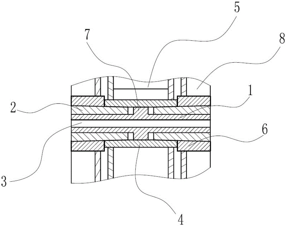
[0015] Such as figure 1 As shown, the embodiment of the present invention relates to a quick-detachable pin shaft structure connecting the guide seat and the base of a large drilling rig, including the base 8, the screw shaft 1 and the male seat 5 connected to the guide seat, and the male seat 5 is located on the base 8 Inside, the screw shaft 1 traverses through the inner hole of the base 8 and the male seat 5, and the inner...


PUM


Abstract

The invention relates to a quick-detachable pin shaft structure for connecting a guide holder with a pedestal of a large-size drilling machine. The quick-detachable pin shaft structure comprises a base, a screw shaft and a male seat connected with the guide holder. The male seat is located inside the base. The screw shaft transversely penetrates through an inner hole of the base and an inner hole of the male seat. A female connector shaft sleeve is installed in the inner hole of the base and located on the two sides of the male seat. A male connector shaft sleeve is installed in the inner hole of the male seat. Threads in the different directions are arranged in outer circle faces of the two ends of the screw shaft, and nut shaft sleeves with the outer sides being tightly attached to the female connector shaft sleeve and the male connector shaft sleeve are symmetrically connected to the outer circle faces of the two ends of the screw shaft through the threads. The outer side wall of each nut shaft sleeve is in a conical shape. The inner circle face of the female connector shaft sleeve and the inner circle face of the male connector shaft sleeve are provided with conical faces matched with the nut shaft sleeves. The quick-detachable pin shaft structure for connecting the guide holder with the pedestal of the large-size drilling machine is reasonable and ingenious in structure, capable of being locked through the inclined faces, convenient to dismantle and not prone to rusting.

Description

technical field [0001] The invention relates to the field of construction machinery connection structures, in particular to a quick-disassembly pin shaft structure for connecting a guide seat and a base of a large drilling rig. Background technique [0002] At present, the connection between the guide frame and the base of the large-diameter engineering drilling rig is realized through a pin shaft, but because of the working characteristics of the engineering drilling rig, this shaft is only rotated when the drill pipe is disassembled, and it is only disassembled when the drilling rig is rotated. The interval between the drilling sites is mostly one month, so the chance of rotation is less, it is easy to rust, and it is very difficult to disassemble, which brings difficulties to the disassembly of the drilling rig. Sometimes because the shaft cannot be disassembled, the shaft can only be cut off and a new shaft can be reinstalled, which is wasteful. A lot of time, and prone ...

Claims


Application Information

Patent Timeline
Patent Type & Authority Applications(China)
IPC IPC(8): F16B13/12F16B39/36
CPCF16B13/124F16B39/36F16B2013/008F16B13/10
Inventor 张良夫吴岳周跃阳张健
Owner ZHEJIANG ZHONGRUI ENG MACHINERY
Learn More