
Robot-based bidirectional feed fixture for door panel bending

A robot and door panel technology, applied in the direction of feeding devices, manufacturing tools, metal processing equipment, etc., can solve the problems that affect the accuracy and efficiency of door panel bending, the automatic door panel bending system is not applicable, hinder production efficiency, etc., and achieve saving Effects of labor cost, quality improvement and production efficiency improvement

Active Publication Date: 2017-09-22
广东佛智芯微电子技术研究有限公司
View PDF1 Cites 0 Cited by
  • Summary
  • Abstract
  • Description
  • Claims
  • Application Information

AI Technical Summary

Problems solved by technology

The robot end fixture in the door panel bending automation workstation, as one of the key components of the door panel bending, is an important part of the robot door panel bending. There are two obvious shortcomings in the prior art about the robot door panel bending: (1) The existing process uses a fixed suction cup fixture, which can only bend one side. After the completion of the bending, the robot places the door panel on the turntable for positioning, and then the robot again deflects to the bent side to grab the door panel, and then bends the second side. Regardless of the prolongation of the bending time or the error caused by multiple positioning, the accuracy and efficiency of the door panel bending are seriously affected; (2) In the existing process, the robot and the bending machine are used together to bend the door panel , however, the execution end of the robot often interferes with the bending machine, which makes it impossible to use the automation system used in conjunction with the robot and the bending machine to bend small panels with a width of less than 420mm, while conventional door panels similar to elevator door panels can only be used for long bending. Side bending cannot automatically bend the wide side with a width of less than 420mm, and these parts that cannot be automatically bent need to be bent manually, which hinders the improvement of production efficiency, and in order to ensure the clamping of the bent door panel by the robot degree of stability, it is unlikely to solve this problem by simplifying the structure of the robot
This patent application can achieve one-time bending of the short side. However, it can only be bent for the short board. It is not suitable for the automatic door board bending system that needs to bend a door board multiple times. It does not solve the existing technology of door board bending. problems in

Method used


Image

  • Robot-based bidirectional feed fixture for door panel bending
  • Robot-based bidirectional feed fixture for door panel bending
  • Robot-based bidirectional feed fixture for door panel bending

Examples


Embodiment Construction

[0021] Below, in conjunction with accompanying drawing and specific embodiment, the present invention is described further:

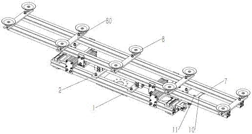
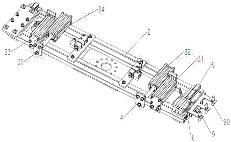
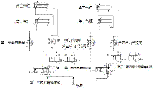
[0022] Such as figure 1 and figure 2 As shown, the robot-based door panel bending bi-directional feed fixture includes a fixed plate 1 for connecting the sixth axis flange of the robot, a fixed mounting frame 2 and a mobile mounting frame 7 arranged on the fixed plate 1, and the fixed mounting frame 2 is provided with a guide rail 5 extending along the width direction of the fixed mounting frame 2 and a driving cylinder group. The guide rail 5 is equipped with a slide block 6 that slides and fits with the guide rail 5. The cylinder assembly includes a piston rod 30 that is parallel to the moving direction. On the first cylinder 31, the second cylinder 32, the third cylinder 33 and the fourth cylinder 34 in the width direction of the fixed installation frame 2, one end of the fixed installation frame 2 is provided with a proximity switch 9, the cylinde...


PUM

PropertyMeasurementUnit
widthaaaaaaaaaa

Abstract

The invention discloses a door plate bending and bidirectional feeding clamp based on a robot and relates to the technical field of door plate bending. The door plate bending and bidirectional feeding clamp comprises a fixing plate, a fixed mounting rack, a movable mounting rack, first air cylinders and guide rails, wherein the fixed mounting rack and the movable mounting rack are arranged on the fixing plate, the first air cylinders are arranged on the fixed mounting rack, the guide rails extend in the width direction of the fixed mounting rack, and a slide block in sliding fit with the guide rails is mounted on the guide rails; the movable mounting rack is arranged on the slide block, connected with piston rods of the first air cylinders and provided with a vacuum sucking disc used for sucking a door plate. The door plate bending and bidirectional feeding clamp is driven by the air cylinders, the movable mounting rack drives the door plate to be bent to be fed in the direction of a bending machine relative to the tail end of the robot, the effect that a fifth shaft of the robot is shifted outward for door plate bending is achieved, and the defect that interference is generated between the tail end of the robot and the bending machine, so that the short edge, smaller than 420mm in width, of the door plate cannot be bent is overcome.

Description

technical field [0001] The invention relates to the technical field of door panel bending, in particular to a robot-based bidirectional feed fixture for door panel bending. Background technique [0002] In recent years, with the continuous development of the domestic economy, labor costs have risen accordingly, and my country's manufacturing manpower advantage is no longer there. Under the background of manufacturing upgrading, "machine substitution" to improve the intelligence of manufacturing industry has become a new trend. The robot end fixture in the door panel bending automation workstation, as one of the key components of the door panel bending, is an important part of the robot door panel bending. There are two obvious shortcomings in the prior art about the robot door panel bending: (1) The existing process uses a fixed suction cup fixture, which can only bend one side. After the completion of the bending, the robot places the door panel on the turntable for positio...

Claims


Application Information

Patent Timeline
Patent Type & Authority Patents(China)
IPC IPC(8): B21D43/18B21D5/00
CPCB21D5/00B21D5/004B21D43/18
Inventor 邓必懋郑思静黄康飞
Owner 广东佛智芯微电子技术研究有限公司
Learn More