
Tower-shaped repairing device of hotly-rolled steel coil

A hot-rolled steel coil and tower-shaped technology is applied in the field of hot-rolled steel coil tower-shaped repairing devices, which can solve the problems of wear of parts, bending of stress points, large driving devices, etc.

Inactive Publication Date: 2016-05-25
SHANDONG IRON & STEEL CO LTD
View PDF9 Cites 4 Cited by
  • Summary
  • Abstract
  • Description
  • Claims
  • Application Information

AI Technical Summary

Problems solved by technology

[0004] First, because the end face of the steel coil tower-shaped defect is not on the same plane, that is, the width of the steel coil on the same diameter is not consistent in the up, down, left, and right directions of the end face. At the beginning, there may be a point contact between the push plate and the steel coil. At this time, all the force of the driving part is applied to this point of action, which may easily cause the point of force to bend and cause secondary damage.
[0005] Second, in the process of tower-shaped restoration, the protruding part does not simply move in a straight line during the retraction process, but retracts while rotating, so that when the steel coil is retracted, the push plate and the steel coil There is a torsional force between the rolls, which will be transmitted to the driving parts during the working process. On the one hand, it is easy to cause wear and damage to the parts. On the other hand, it is laborious to apply and requires a larger drive device, resulting in waste of cost

Method used


Image

  • Tower-shaped repairing device of hotly-rolled steel coil
  • Tower-shaped repairing device of hotly-rolled steel coil
  • Tower-shaped repairing device of hotly-rolled steel coil

Examples


Embodiment Construction

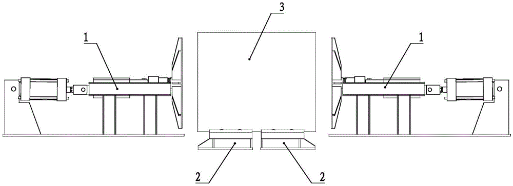
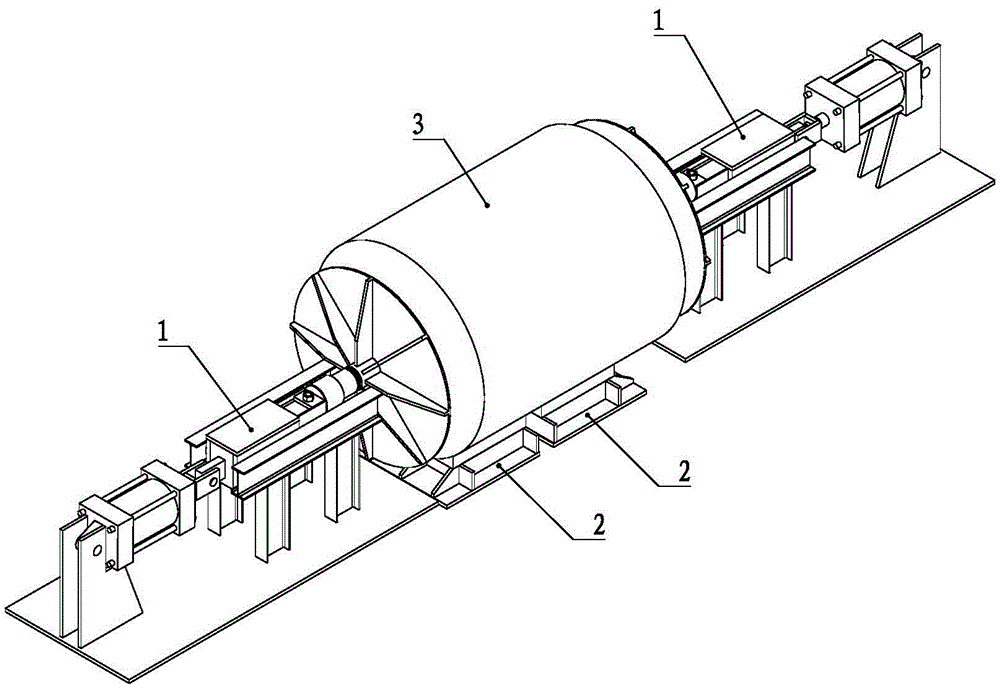
[0039] Such as Figure 1 to Figure 3 As shown, a hot-rolled steel coil tower repair device includes a side thrust mechanism 1, a saddle 2, a power system and a control system. The saddle 2 is used to place the steel coil 3, and the number of the saddle 2 is two, and the saddle 2 can move along the axial direction of the steel coil 3, so that it is mainly for adapting to steel coils of different widths 3. To increase the scope of application of a hot-rolled steel coil tower repair device. The side pushing mechanism 1 is respectively arranged on both sides of the saddle 2, and exerts force on the steel coil 3 with tower-shaped defects from both sides during operation, so as to eliminate the tower-shaped defects of the steel coil. The side thrust mechanism 1 is respectively connected with the power system and the control system.

[0040] Such as Figure 4 to Figure 6 As shown, the saddle 2 includes a base 21 and a mounting plate 22, the base 21 is provided with a V-shaped pad ...


PUM


Abstract

The invention provides a tower-shaped repairing device of a hotly-rolled steel coil and relates to the technical field of steel coil defect correction. The tower-shaped repairing device comprises lateral pushing mechanisms, a saddle, a power system and a control system, wherein the saddle is used for storing the steel coil; the lateral pushing mechanisms are arranged on the two sides of the saddle respectively. Each lateral pushing mechanism comprises an air cylinder base, an air cylinder, a trolley, a guide rail, a guide rail support, a push plate and a base plate. A cylinder body of the air cylinder is hinged to the air cylinder base; a piston rod of the air cylinder is hinged to the trolley through a U-shaped connector; the trolley can move along the guide rail; an arm of the trolley is connected with the push plate through a floating connection piece. According to the tower-shaped repairing device provided by the invention, the floating connection piece is additionally arranged between the push plate and a driving part, so that point contact between the push plate and the steel coil can be avoided, and the push plate can be completely filled with a convex part of the steel coil all the time in a repairing process, and a movement track of the steel coil is completely fitted; a condition that part abrasion is caused by the fact that a twisting force is transmitted to the driving part is avoided, and labor is saved in a use process of the tower-shaped repairing device.

Description

technical field [0001] The invention relates to the technical field of steel coil defect correction, in particular to a tower-shaped repair device for hot-rolled steel coils. Background technique [0002] The tower defect is the most frequently occurring defect in the production process of the hot rolling mill's skin pass line. This kind of defect will not only affect the appearance quality of the steel coil, but also easily cause the edge of the steel coil to be broken during the lifting process of the crane using the tongs, resulting in secondary damage. In order to repair the tower shape of the steel coil, workers usually use a sledgehammer to manually knock the repair, which is not only labor-intensive and inefficient, but also the effect of eliminating the tower shape is difficult to meet the standard. [0003] Aiming at this situation, the patent No. 200920208839.9 discloses a steel coil inner tower correction device. The device includes a bracket, a bottom plate, a ...

Claims


Application Information

Patent Timeline
IPC IPC(8): B21C47/26
CPCB21C47/26
Inventor 张焱李扬王宝林刘长川李忠伟彭伟明武国栋
Owner SHANDONG IRON & STEEL CO LTD
Learn More